Click on any picture to open a slideshow. Once there, you can click the link in the caption for the full-size picture.
With the workbench build complete, it was finally time to assemble the CNC and get it up and running. It was a long path to get to this point - clear out the space, electrical work, assemble the new dust collector, and build the torsion box top.
| Assembly and Prep | |
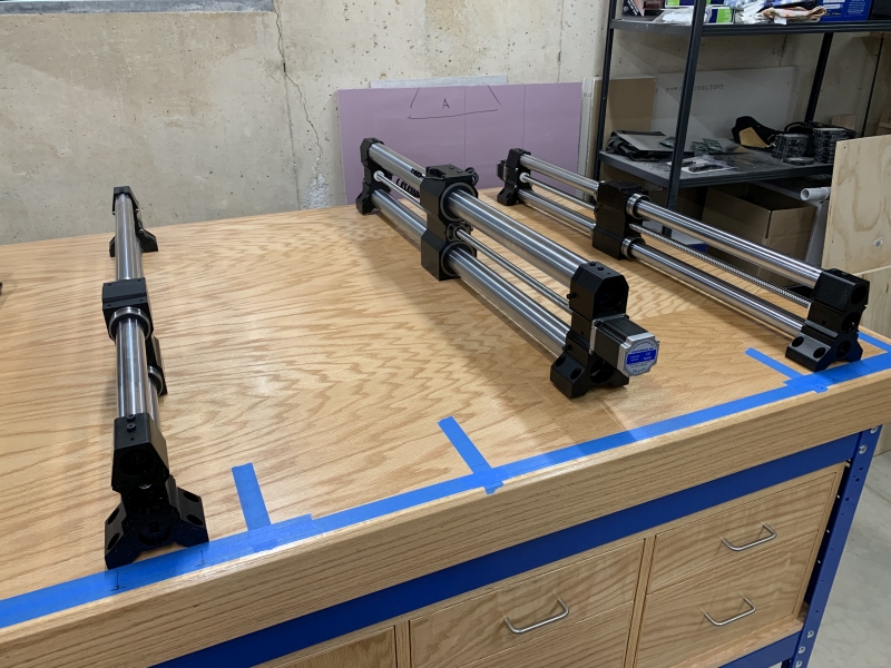 Two weeks after the CNC arrived I am finally starting to assemble it. The blue tape is how I mark the locations of the stringers inside the top to line up the CNC accurately so that it is solidly screwed down. |
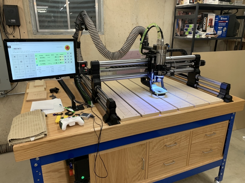
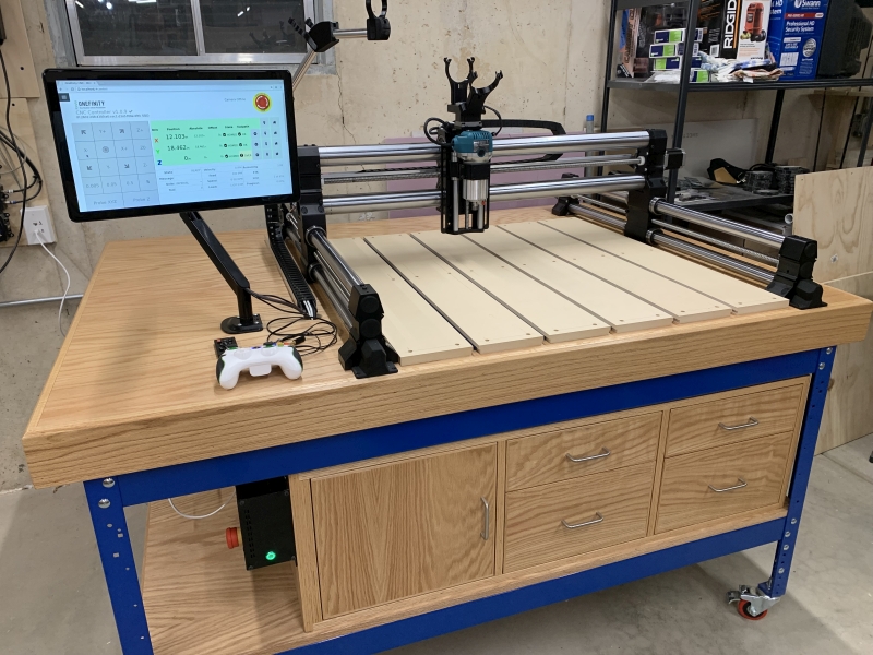 Here is the CNC fully assembled, wired up, and running. At this point I still had to install the dust collection hose. I am starting out using a small Makita router which the CNC is designed for. They work well, but they are not designed to be run for hours at a time like they will in a CNC. People get less than 100 hours before having to replace the brushes. |
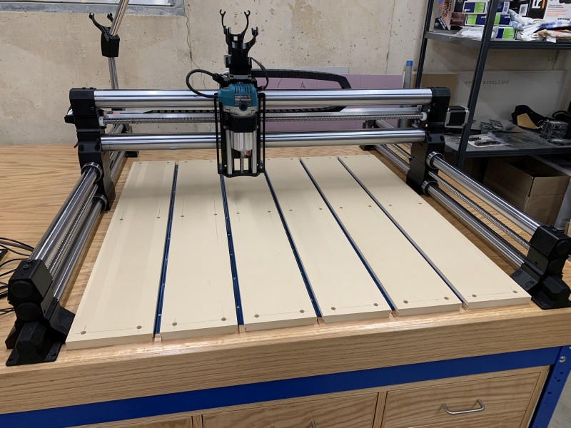 The lighter wood is the MDF spoilboard. The workpieces to be carved/routed will mount to that and if I have to cut through them the bit will cut the spoilboard without ruining the bench top. It is meant to be sacrificial and easily replaceable. |
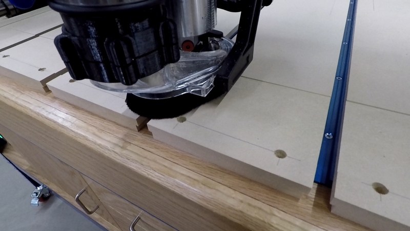 The next step is to flatten the spoilboard. This takes out any irregularity in the workbench top (mine had a slight hump of .020 inches) and leave the spoilboard completely flat and the same distance from the router at all points. Before doing this cut, I did what is called an "air cut". I ran a job with the router set to not cut into anything but air. I wanted to make sure the machine moved exactly as I expected. It did, so I proceeded to install this program and run it. |
|
Spoilboard Flattening - YouTube |
 I wanted to cut a grid of 2-inch squares in the spoilboard to assist in lining up workpieces so that they are square to the machine. I was going to cut them with a small v-bit. By its nature, a v-bit will cut a wider line the deeper it goes. This was a test I did at three different depths to see how small of a line would still be useful without being too deep. |
 Here is the completed spoilboard ready to be put to work. |
Spoilboard Grid - YouTube |
 One last test cut. The purpose of this is to measure the accuracy of the cuts. The circle is 5-inches in diameter and the square is 6-inches. These were within .003 inches. That's close enough for me! |
|
| First "Project" | |
| Now
that all of the
prep and testing was done, I actually said out loud, "Ok, what's next?"
And I realized I didn't have anything planned. So I
quickly
designed this sign. I used 3 different fonts to see how
v-carving
would look with each. With V-carving, the CAD/CAM software calculates where to cut to carve out the lettering. It adjusts the depth of the v-bit so that edge cuts right at the outside lines of the letters. I did find out later that I have the incorrect year - it was actually 1988 when I started woodworking as a hobby. |
|
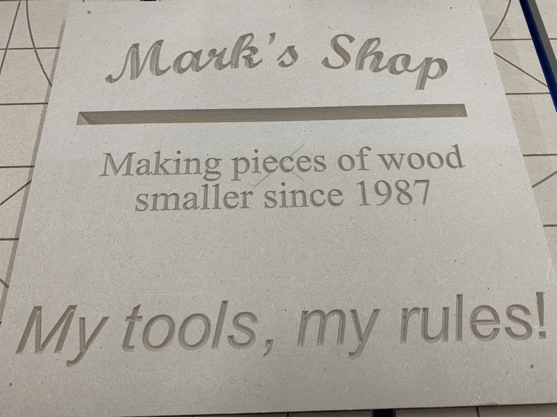 This is soft MDF, but it was neat to watch how precisely and cleanly it carved this text. |
 You can see in the very corner of the letters how the v-bit raises up to cut them precisely. It isn't very deep there. |
|
V-carve Sign - YouTube |
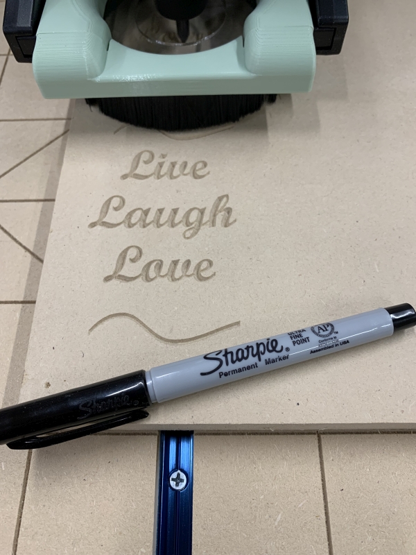 Then as a joke I made this small sign for a friend at work. At one point during the whole workbench build process he jokingly asked, "So when are you going to be ready to start making Live, Laugh, Love signs?" My answer was "Never!" So I had to do this for him. I also wanted to see how small I could go - and I'm sure this could be done a lot smaller and still be crisp. |
| Spindle Installation | |
| My
plan all along was
to eventually replace the Makita router with a spindle. As I
was
working on the bench, the online source for these got more in stock so
I placed my order. I decided not to wait to install it. This is a 220v 2.2kW water-cooled spindle. It is run through a VFD (Variable Frequency Drive) which controls the speed and compensates for the load placed on the motor. The advantages of this over the router are: - Much more powerful. The spindle can handle larger bits. - Much quieter. The small routers are loud. The water-cooled spindles are considerably quiter, but the cutting noise is much the same. - Spindles can run at slower speeds more efficiently. - The spindle interfaces with the CNC controller and the CAM software. The software tells it when to start, how fast to run, and stops the spindle at the end of the cutting. With the router, I had to adjust the speed manually with the dial and turn it on/off manually. |
|
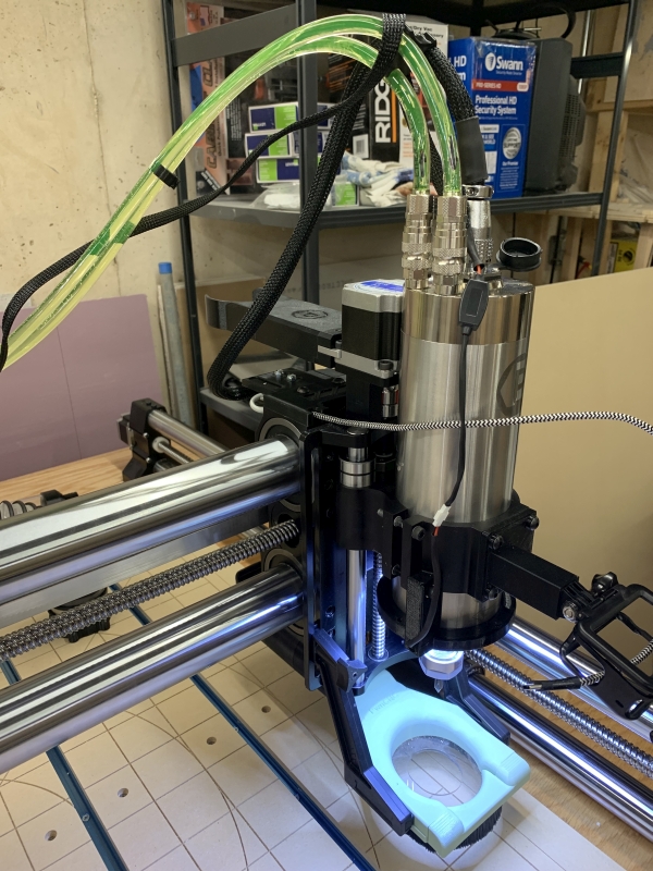 The spindle is significantly larger and heavier than the little router. It is larger in diameter - I had purchased the larger mount with the CNC. The one-man company I purchased the spindle kit from did all of the hard work of sourcing the correct cables and doing the testing and programming. I also purchased what he calls "Kool Connectors" for the coolant lines. They allow me to disconnect them without coolant flowing all over the place. The power cable for the spindle is quite a bit thicker than the cord for the router. That and the tubing wouldn't fit in my cable management and I didn't like them hanging like that. More on that later. |
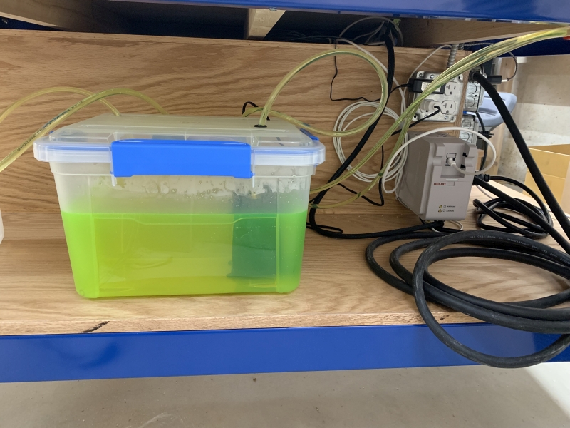 I found these waterproof containers at Home Depot and figured it would work better than a bucket to hold the coolant and pump. The pump is just a small pond pump. After installing it I realized I needed an easy way to turn it on/off. I had to modify my electrical to add a switch and separate outlet for it. I also installed the LED ring light I purchased on Etsy and plugged that into the switched outlet. That way I know if the light is on the pump is too. You can use straight distilled water, but I chose to use anti-freeze and distilled water to provide some rust protection. |
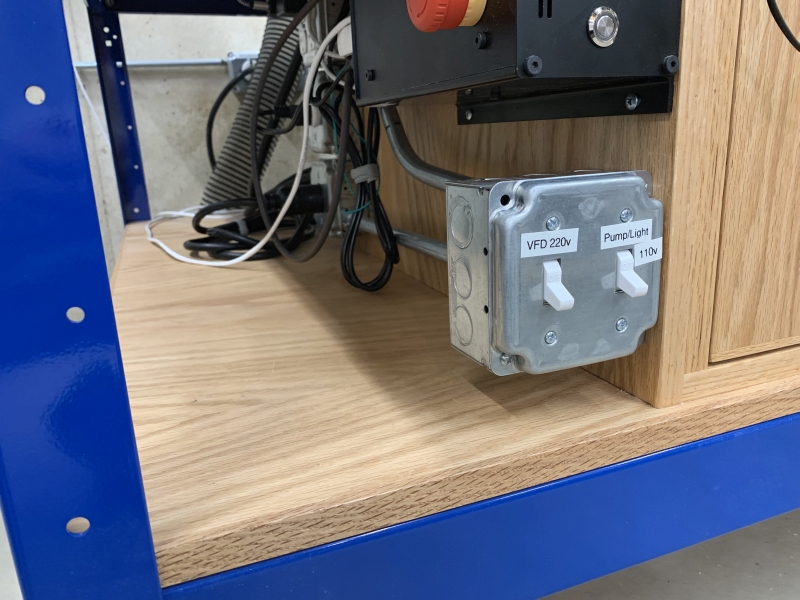 I originally started out with just one switch here... |
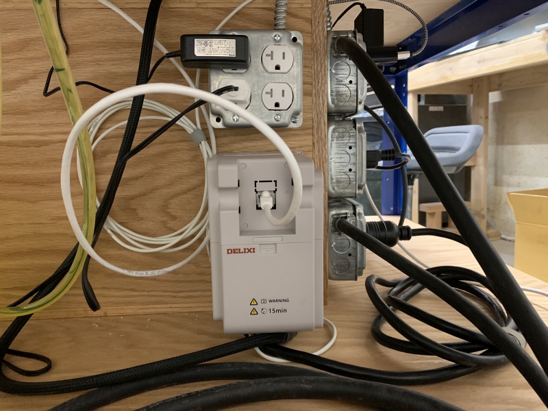 This is the VFD that runs the spindle. I learned that it doesn't have an on/off switch. So I had to revise the electrical yet again to switch the dedicated 220v outlet that this plugs into. Where the white Ethernet cable is plugged into the VFD is where the small control panel plugs in. It is designed so that you can remotely mount the control panel. |
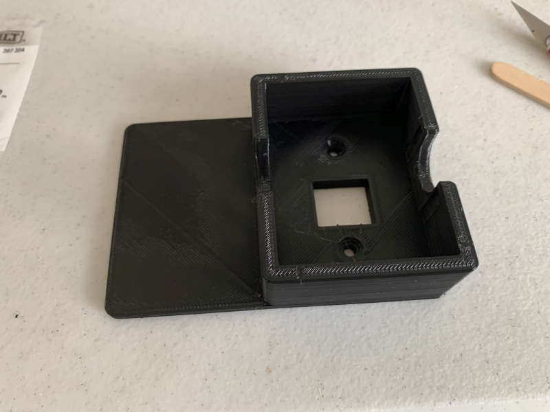 The company that I bought the spindle kit from also sells flush or surface mounts for the panel. By this point I had learned how to use my 3d printer and the design software so I purchased his digital files to 3d print it myself. I printed one but the panel fit very tightly. I also decided I didn't want to surface mount mine, so I changed the digital file to make the opening .5mm larger and added the flange on the left. |
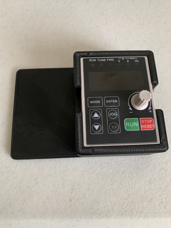 Here is the control panel in the mount. |
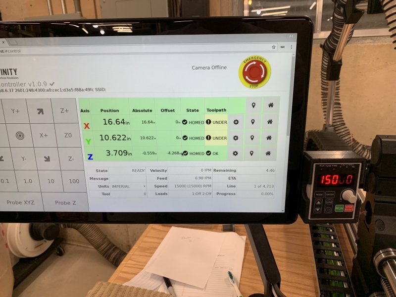 And here is why I added the flange. I used double-sided mounting tape to stick it to the back of the monitor so that the panel is right where I need to see it. Because the software is controlling the spindle I don't have to touch the control panel, but it shows the speed as confirmation it is running at the correct speed. More importantly, it flashes when the spindle is "off" so I know it is safe to change bits. |
 I was now in full-on 3d printing mode. A lot of the accessories for the CNC are created by makers and sold on Etsy. I purchased the digital files for this GoPro mount and modified it to better suit the spindle. I had to change the base where it screws into the spindle mount, and added the arm to move the GoPro out a little. |
 Ready to go with the spindle set up. |
 In an email exchange with another Etsy vendor, I learned that he had created new files for the drag chain add-on since he had also purchased a spindle. He sent me the files for free so I started printing all of the brackets and ordered the larger drag chain. |
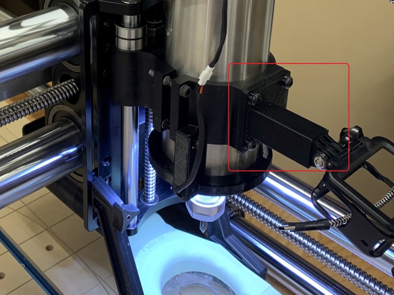
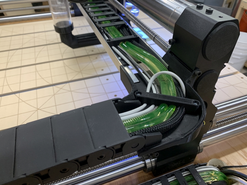 The brackets attach to the CNC and hold the aluminum angle that the drag chain rides on. This bracket makes the turn from X-axis to Y-axis. These are now large enough to hold the spindle power cable and the coolant lines. The other cables are the power cords for the ring light and GoPro, and the white cables are the ones that control the CNC stepper motors. One thing I did have to modify from his files were the cable hold-down clips. They weren't sized for these cables. It was a further learning experience for me with the 3d printer CAD software. |
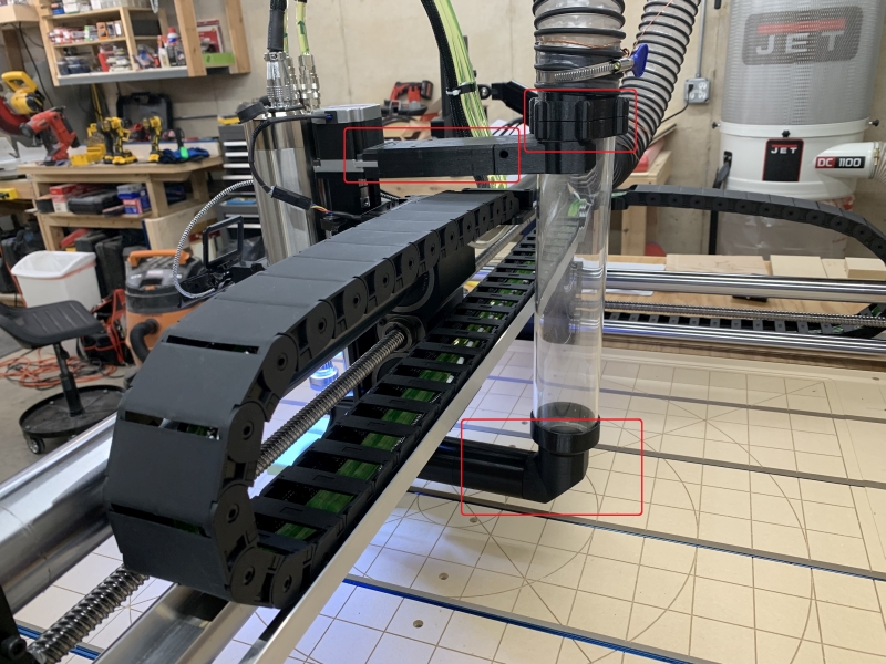 This is a good picture of some of the add-on accessories available on Etsy. A lot of these are 3d rinted. The dust collection boot, tube, and holders all came from the same guy that sells the spindle kits. I had already modified the top bracket prior, but now with the larger drag chain I had to make it even longer. At the top of the clear tube, those adapters have magnets to join them. I had to print those. At the bottom of the tube, I had to print the longer black tube to extend past the drag chain. |
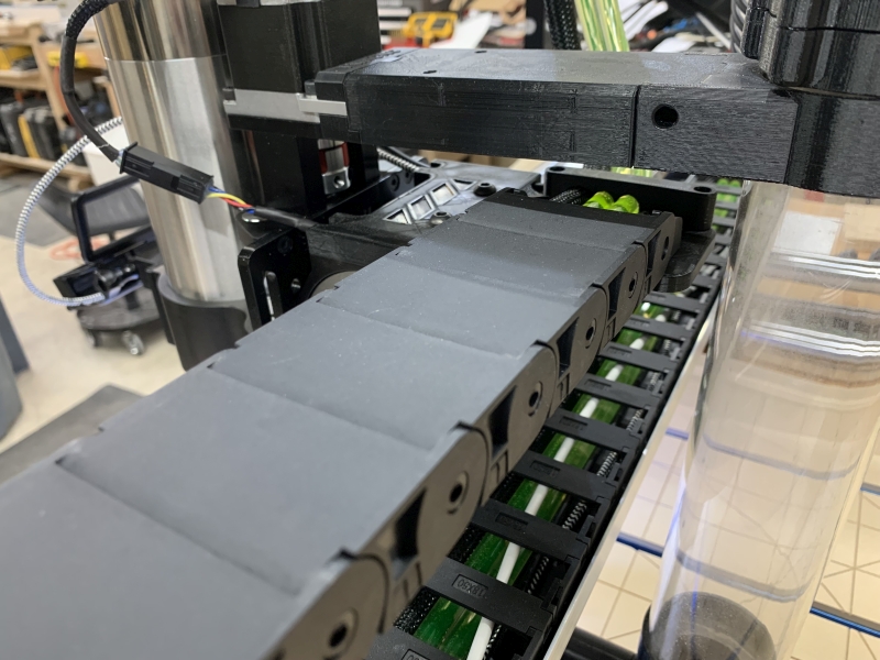 My 3d prints don't turn out as polished as what he sells, but they're functional. |
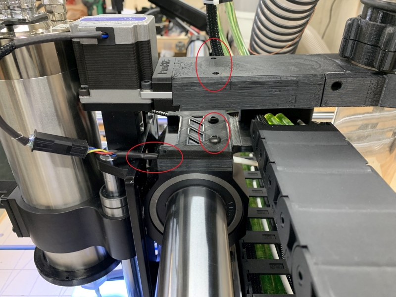 Here are more examples of how I modified their designs. The top piece is from one person and the bottom bracket (that the drag chain mounts to) comes from someone else. I learned that the top piece blocks access to the screws on the bracket and I had to disassemble that any time I needed to take off the bracket. When I modified it to make it longer I added holes through it so I have access. I also modified the bracket to accommodate the cables I have. I love being able to make changes and print my own parts! |
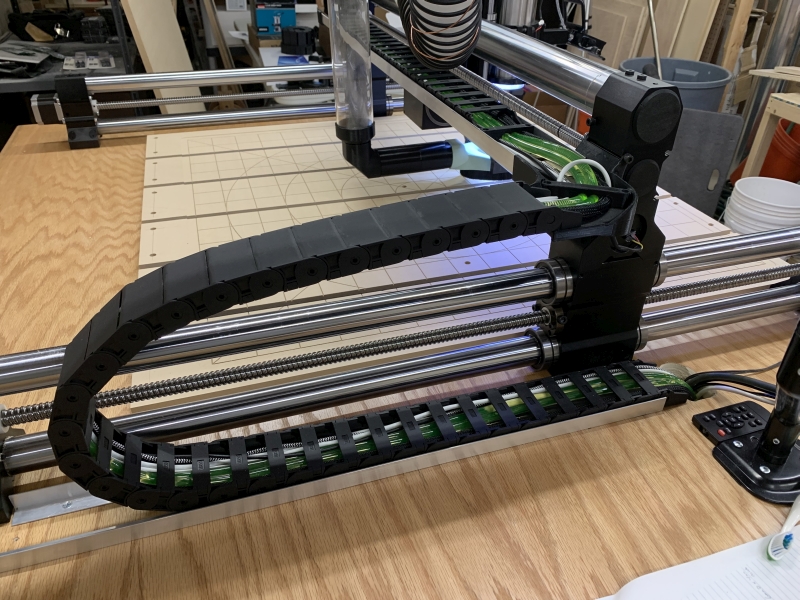
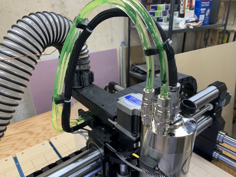 Here is a good shot of how the spindle cable and coolant lines now route into the drag chain. I added the flow direction arrows, but it doesn't matter which direction it flows. |
 One last modification. The hose boom was purchased from yet another person on Etsy. The pipe is actually a shower curtain rod. I cut a longer piece to raise the hose higher to keep it out of the way. |