Click on any picture to open the full-size picture in a new tab.
I wanted to use my Incra router table fence system to build decorative pc speaker boxes. I ordered an inexpensive speaker set on Amazon, took them apart, and set out to build better looking boxes.
 |
||
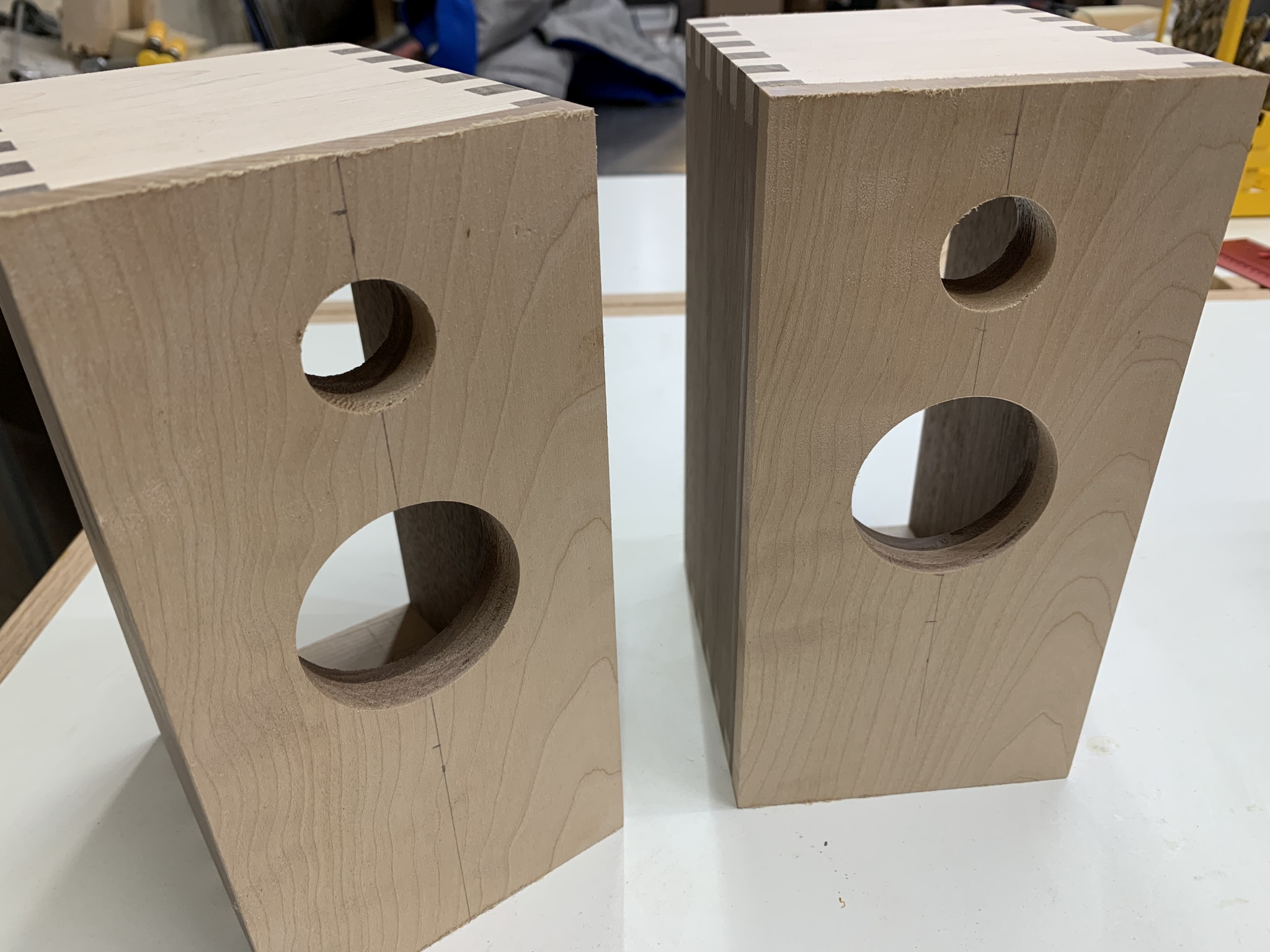
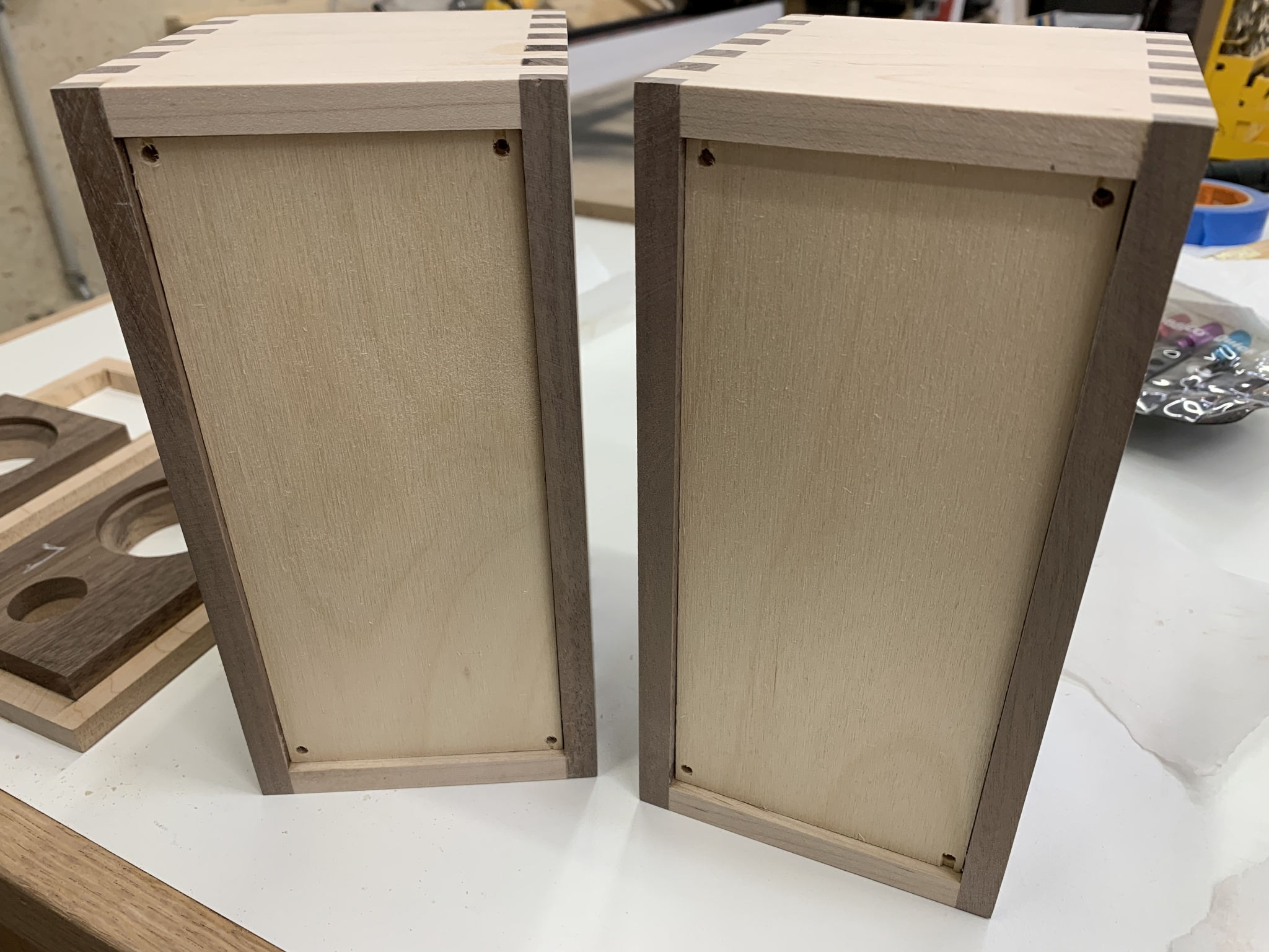
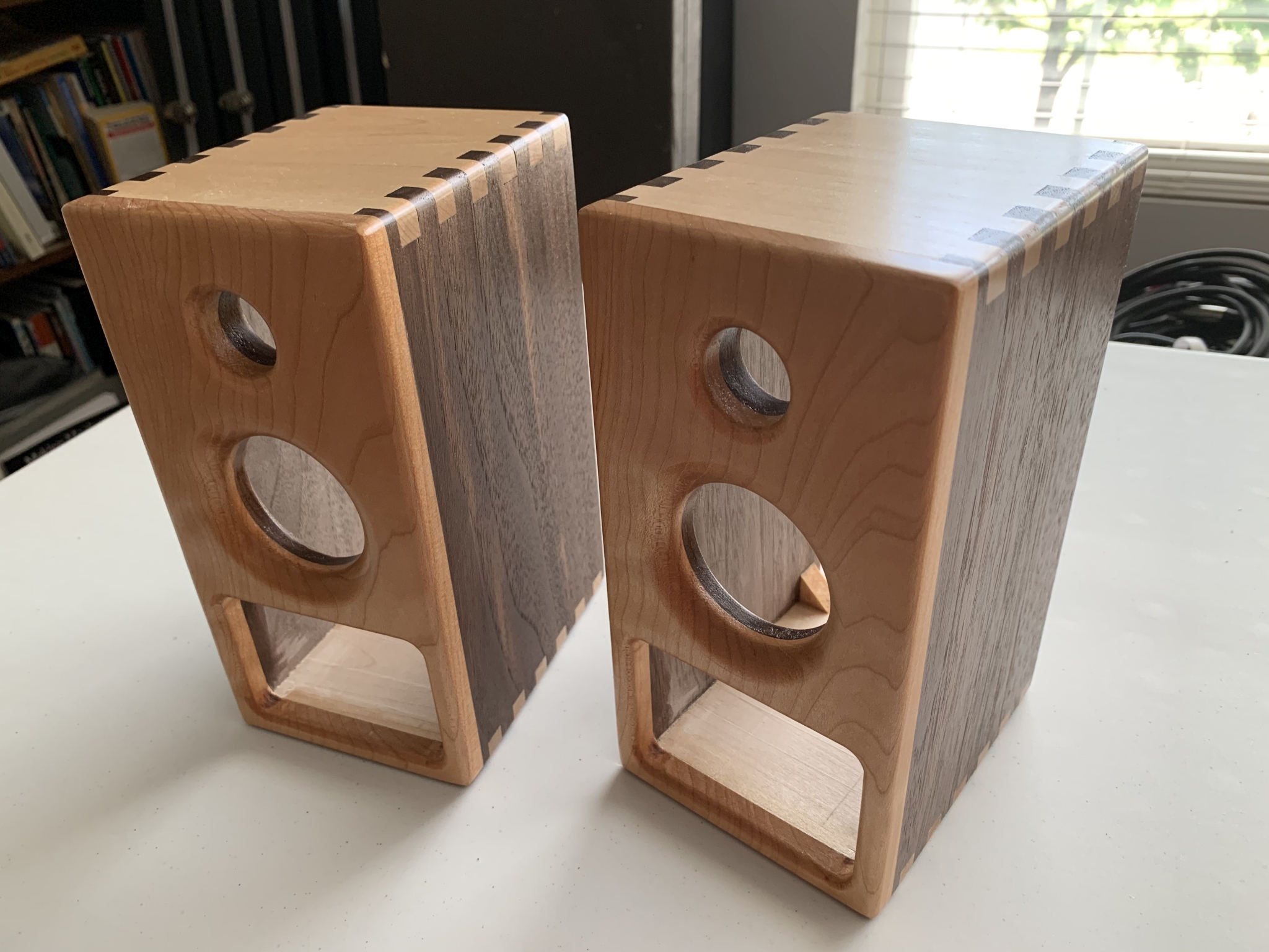
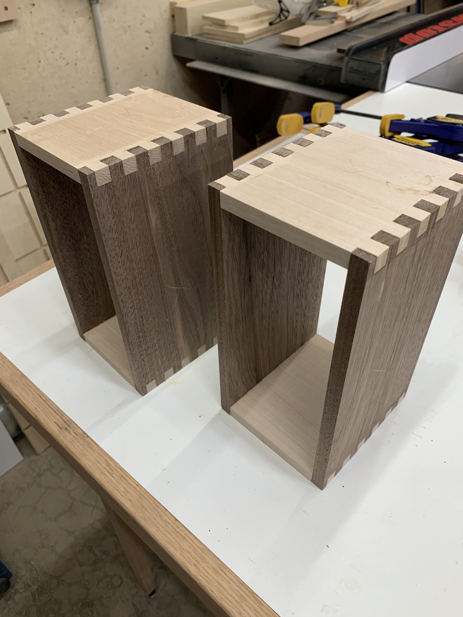 1. Here are the cases made from walnut and maple using box joints. These are 8"H x 4"W x 4-1/2"D. I didn't take pictures of this process. |
 2. I cut a section of the front panels out so I could reuse the control panel and circuit board that mounts behind it. |
 3. Here is how the panels will fit in the boxes. |
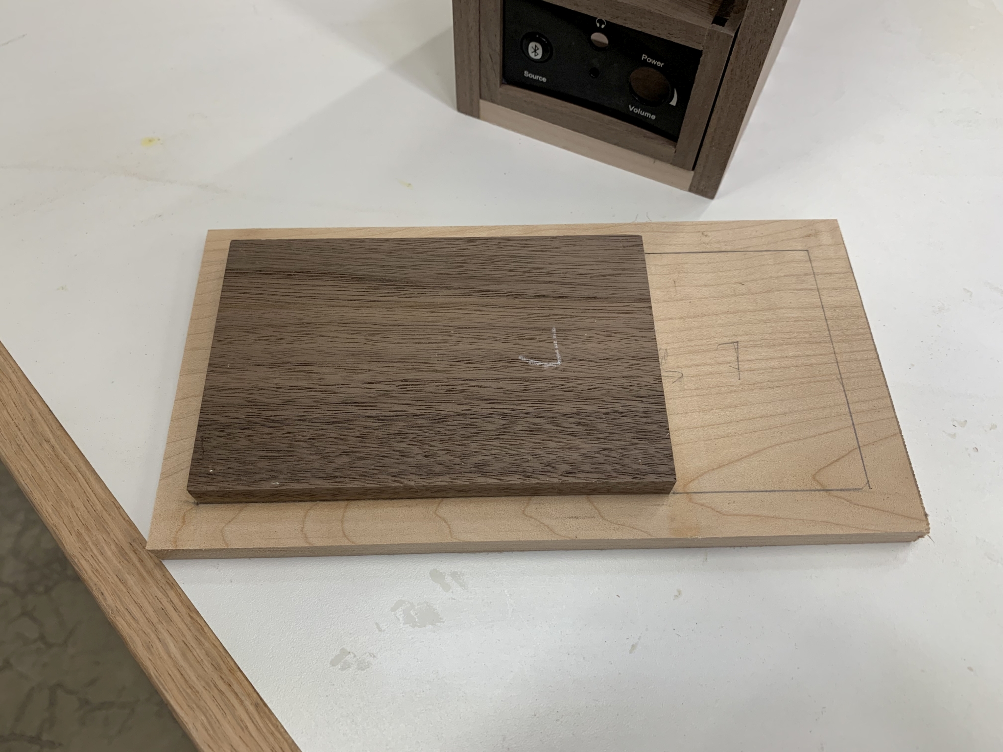 4. The front panels will be curly maple. I wanted a layer of wlanut to show behind it through the openings for the speaker and sound port. |
 5. Test fitting the front to the boxes. The front is slightly oversized. |
 6. Using a flush trimming bit in the router table to flush the fronts to the boxes. |
 7. After flush trimming. |
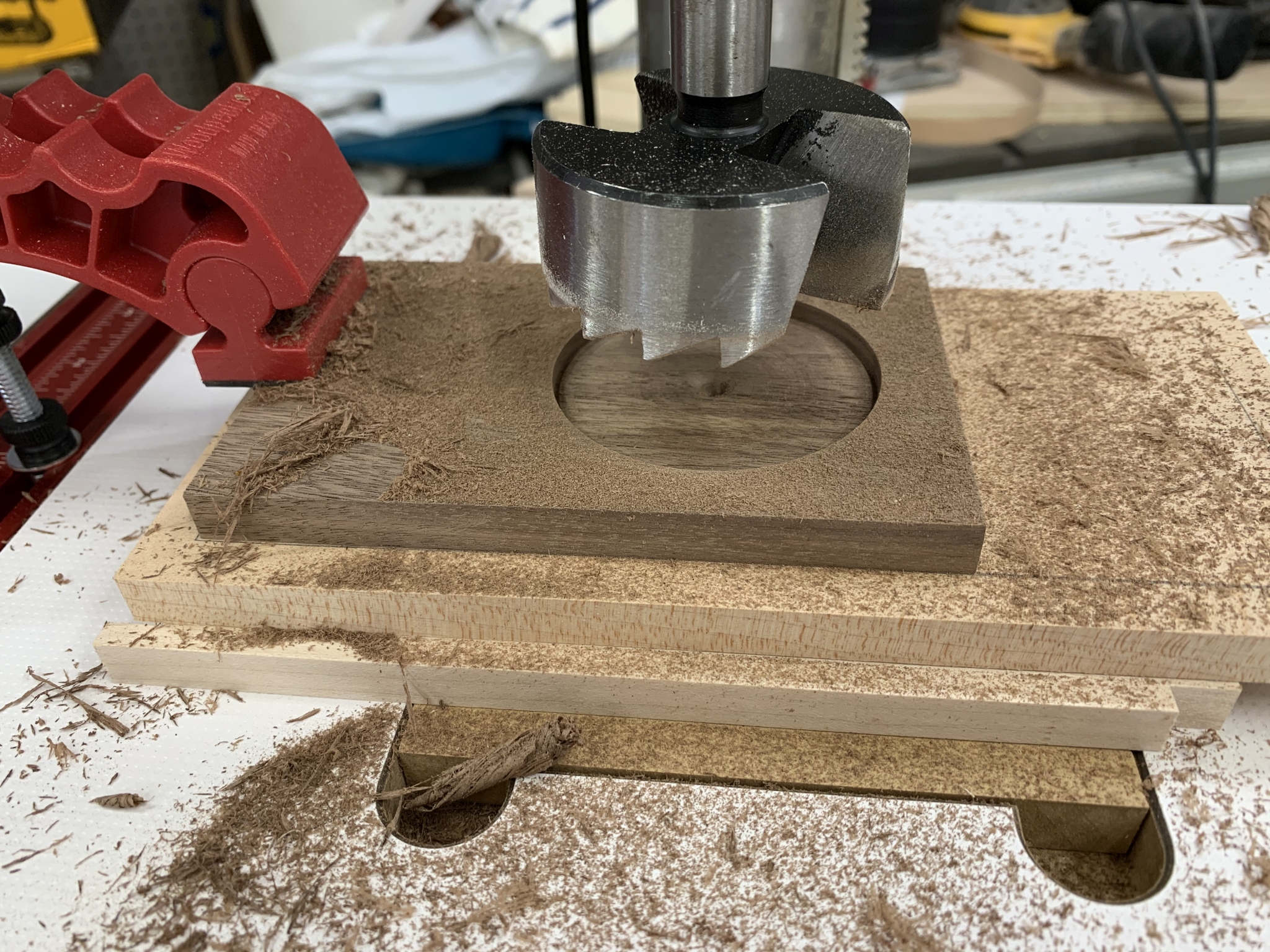 8. Drilling the larger indentation for the speakers. |
 9. Testing the depth. |
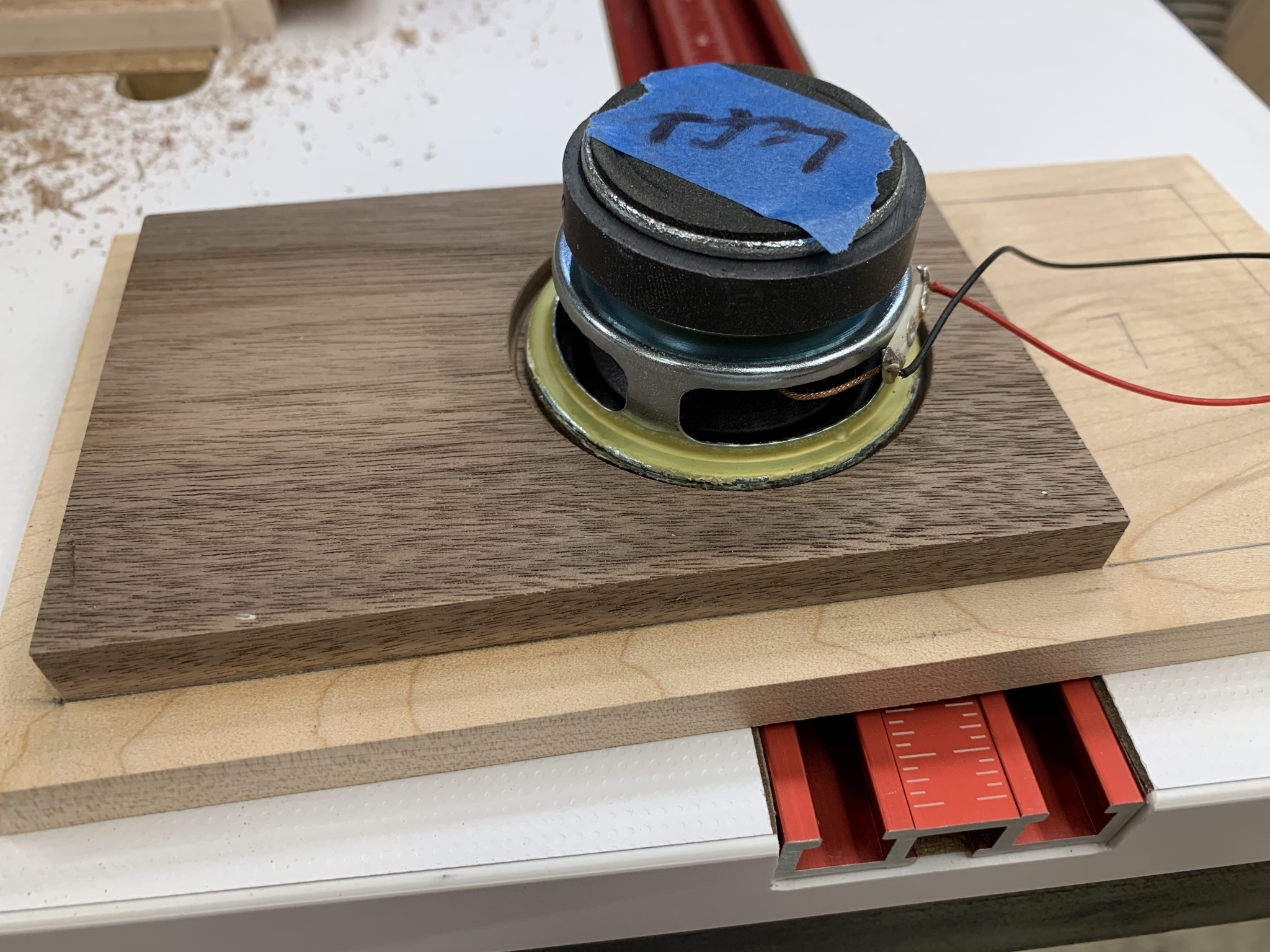
 10. After drilling a slightly smaller hole all the way through. |
 11. A little hard to see here, but this is what it will look like. I should have made the fronts thinner, but rounding over the edges will help expose more of the speaker. |
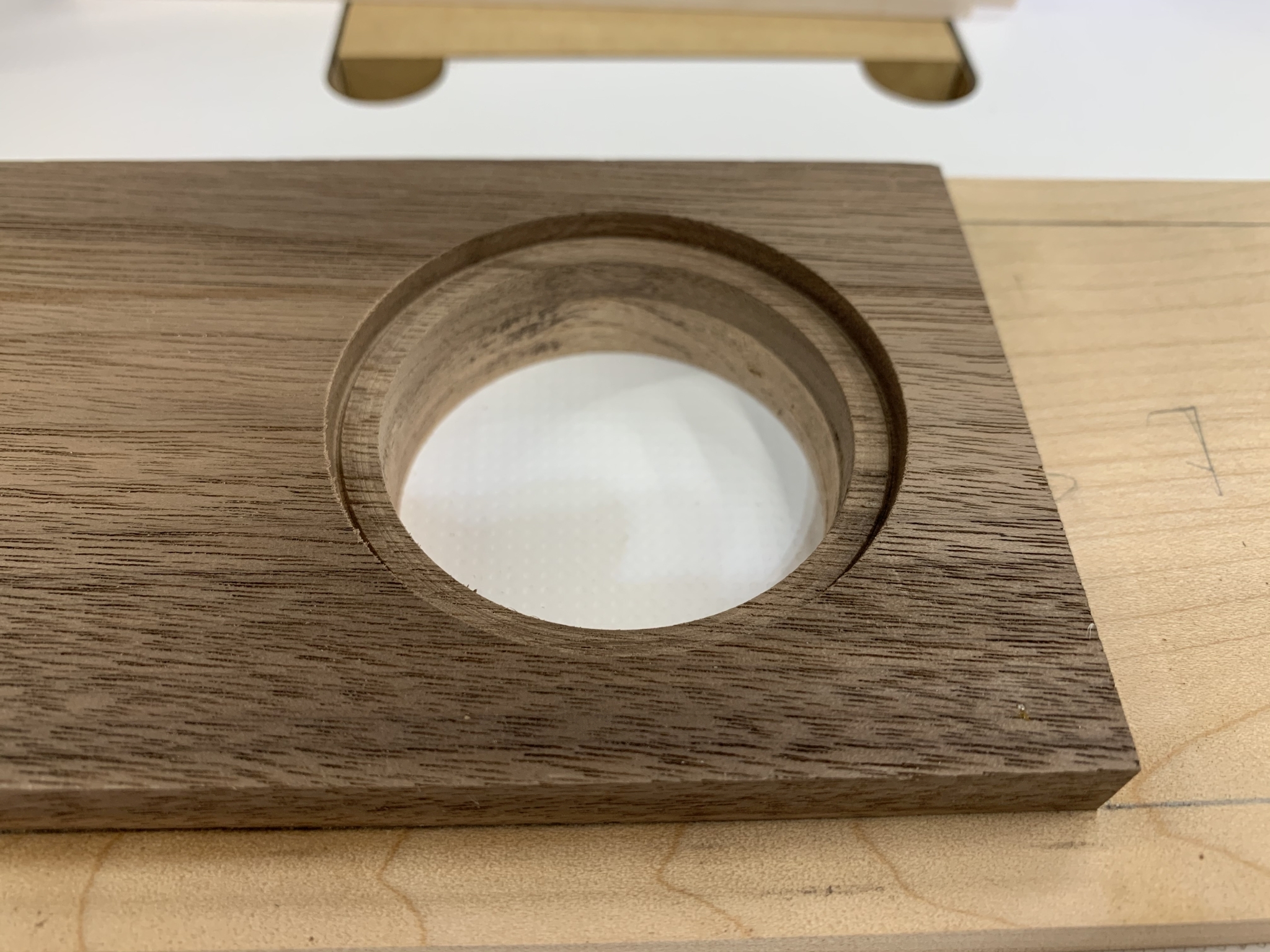
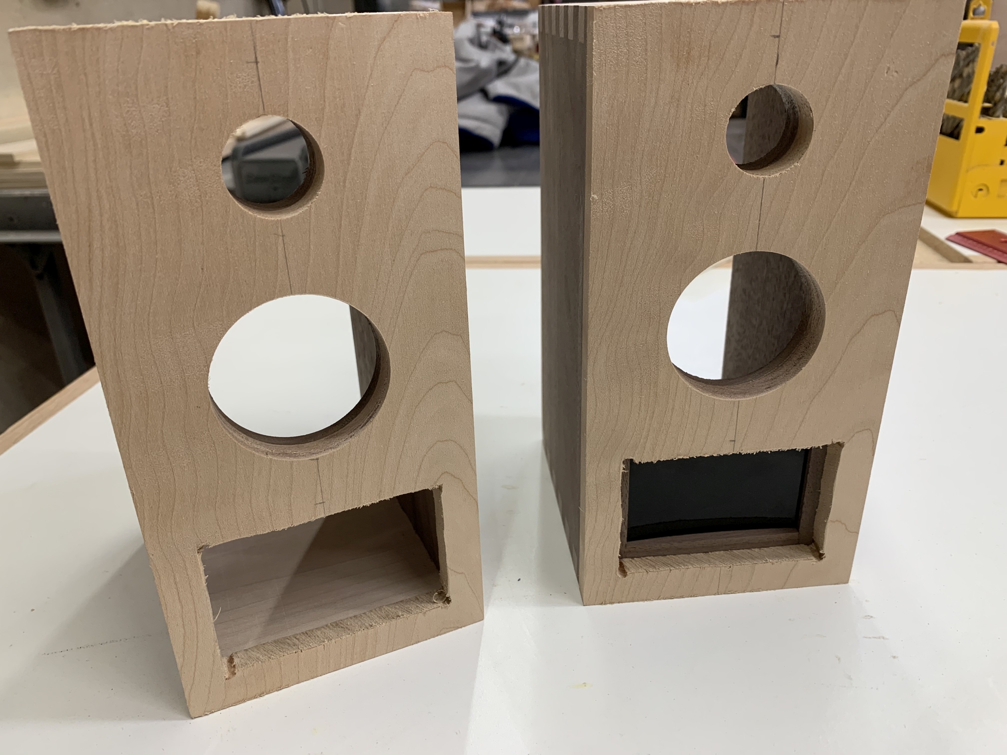
 12. After drilling the sound port holes. |
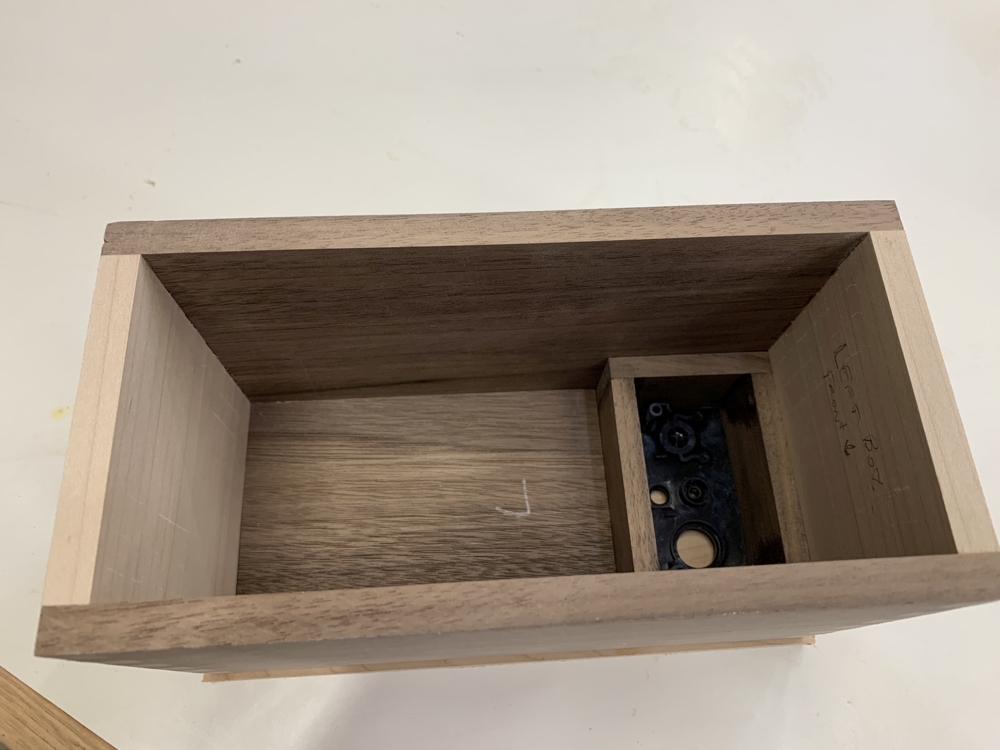
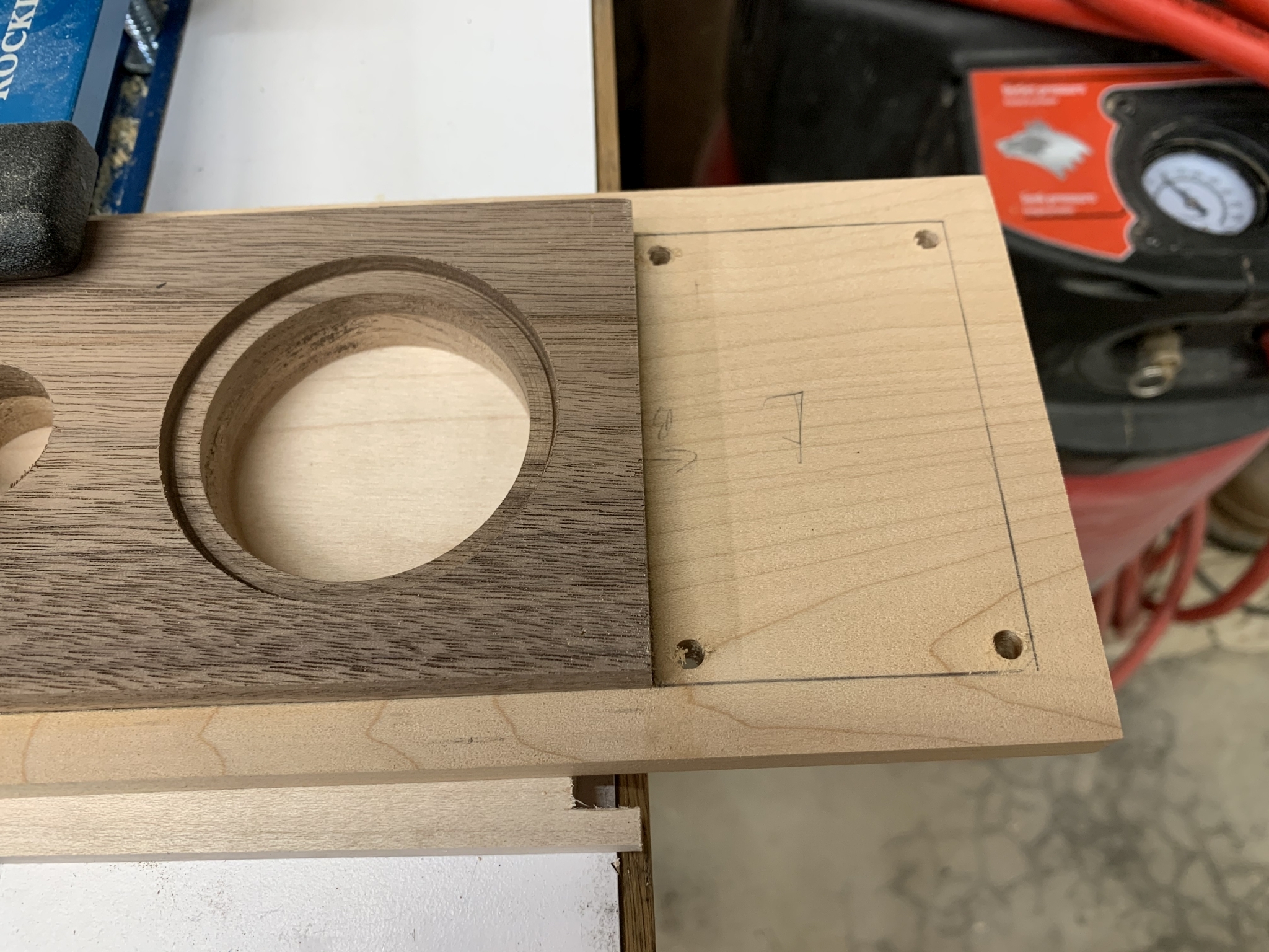 13. Next I needed to remove the area where the panels will sit. |
 14. I used a coping saw to cut the opening, leaving 1/8" to be flush trimmed. |
 15. Getting a feel for how this will look. |
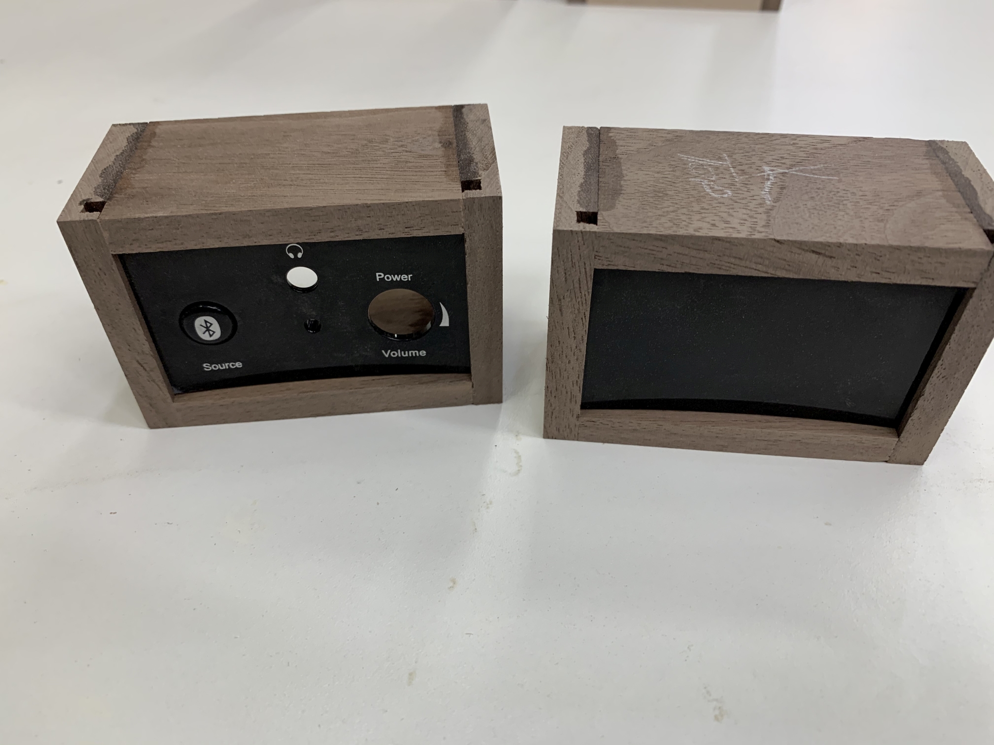
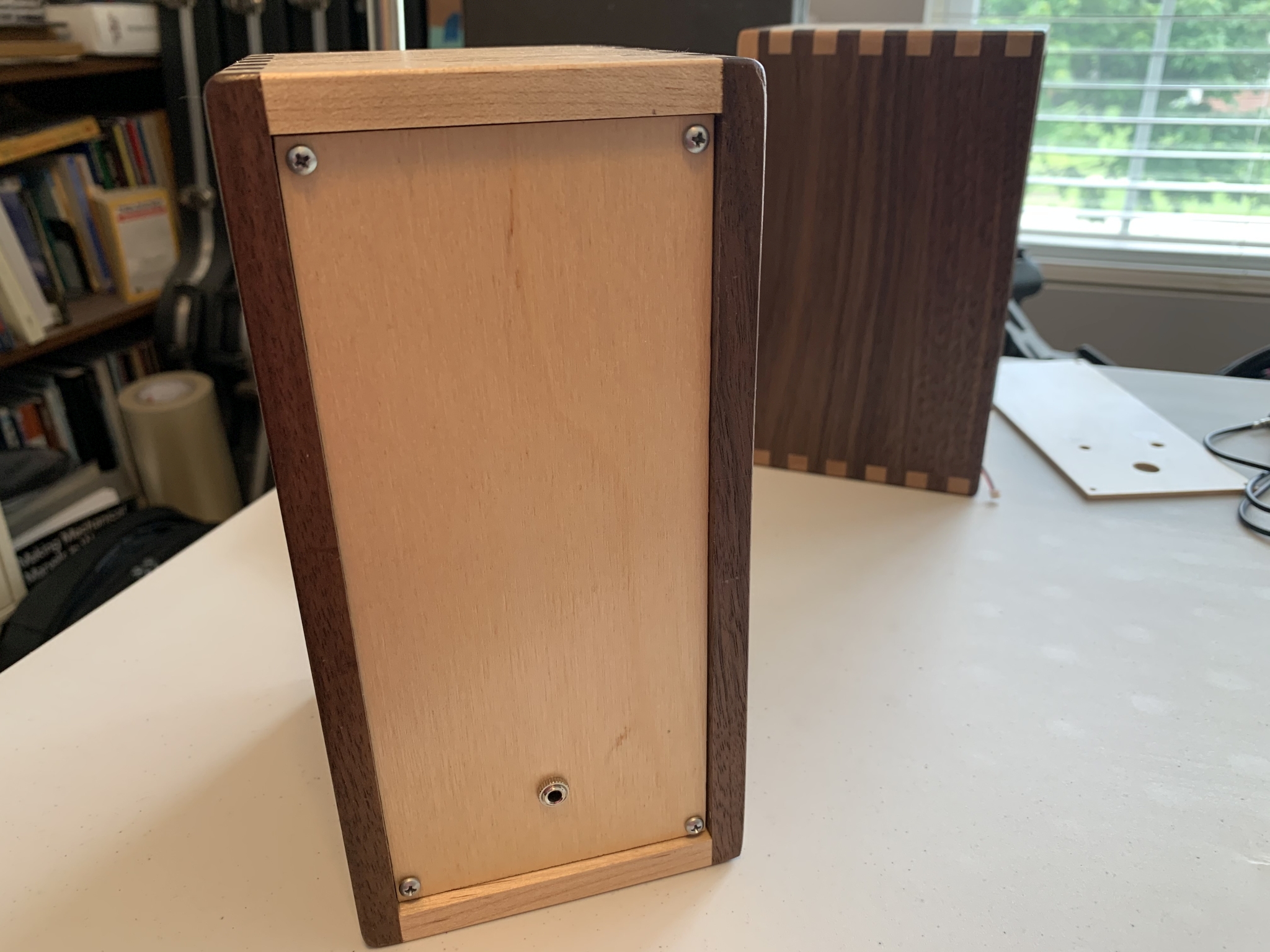
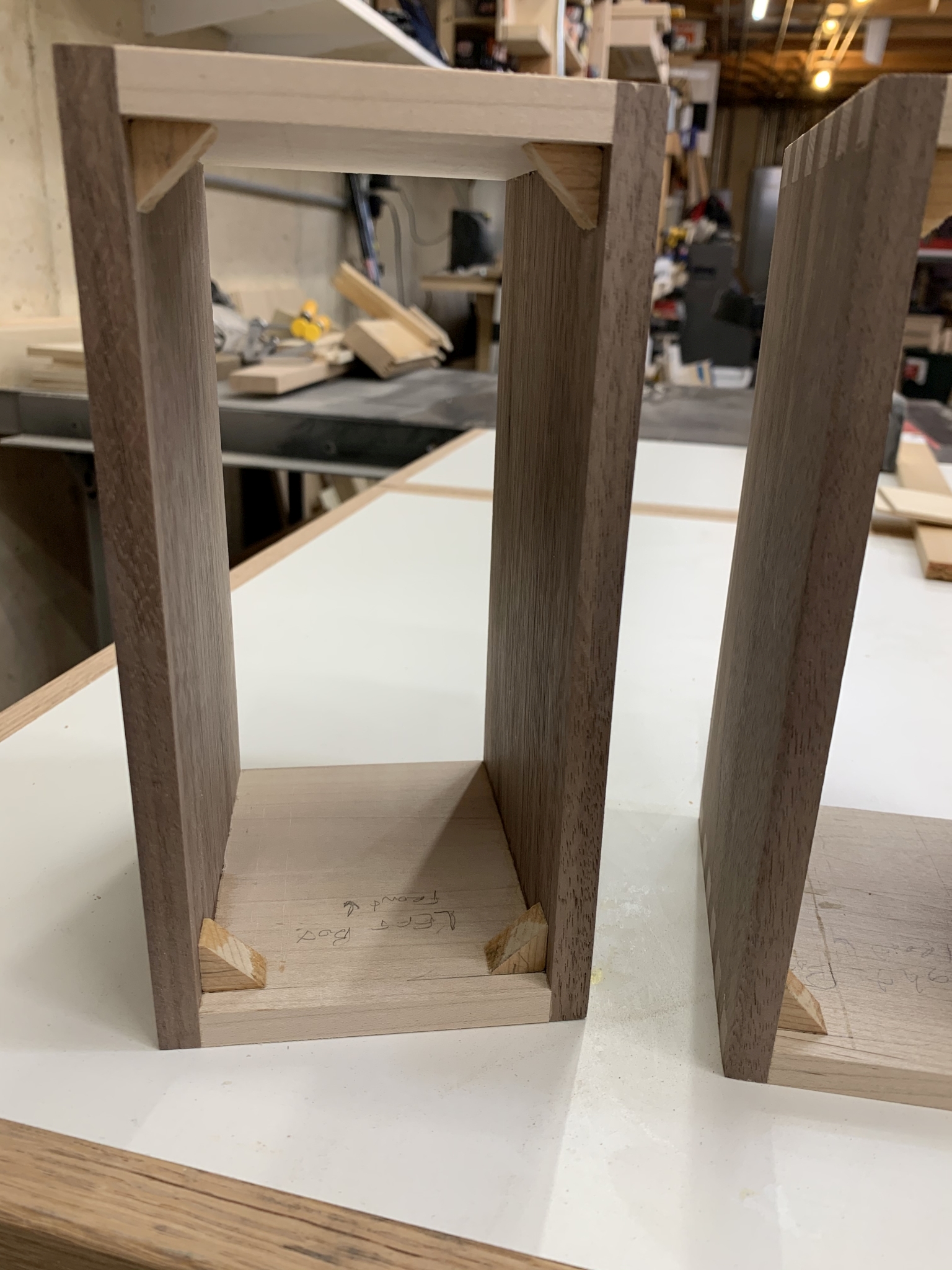 16. Before I glue the fronts on, I need to glue blocks inside for the backs to attach the backs. |
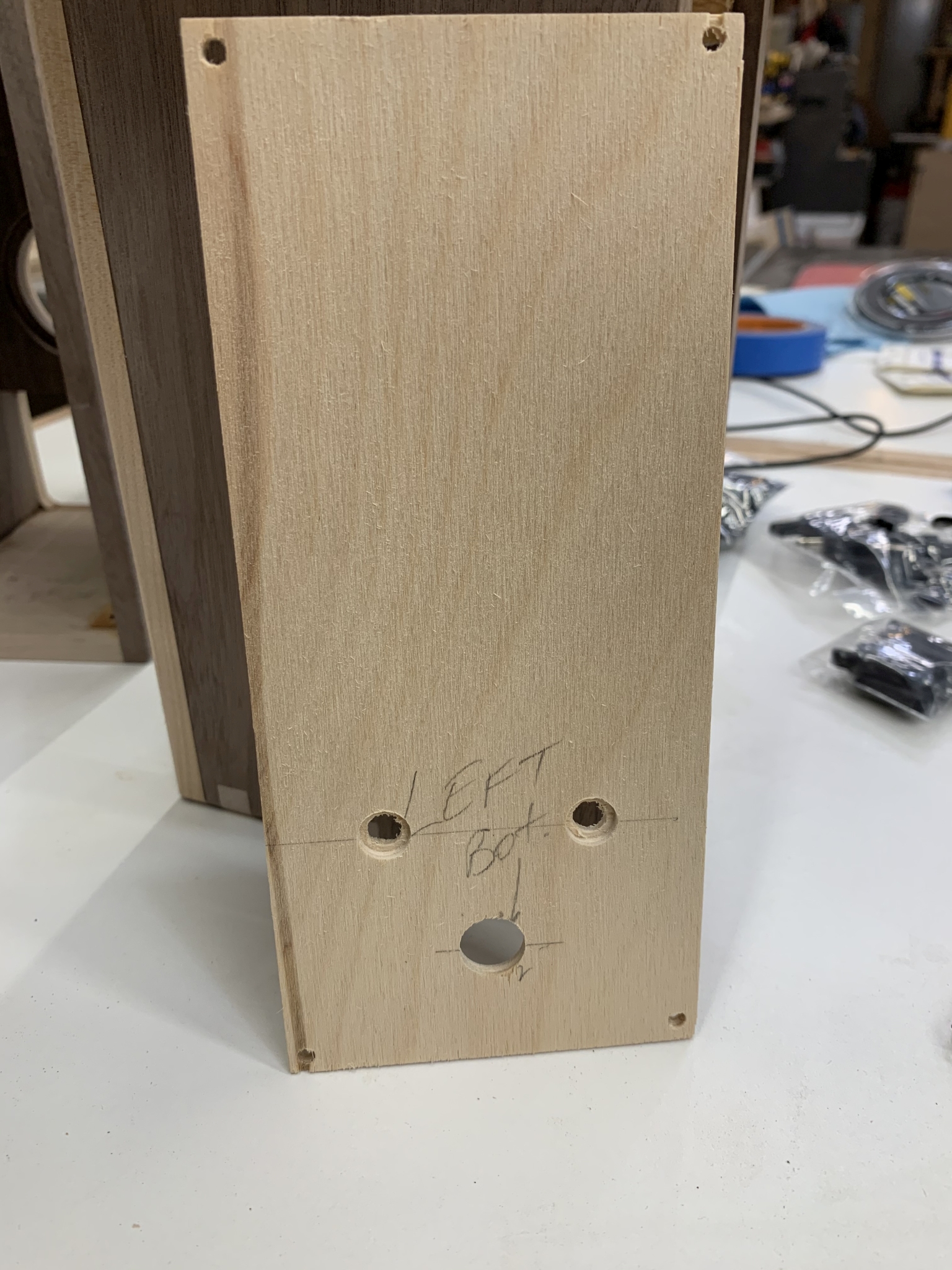
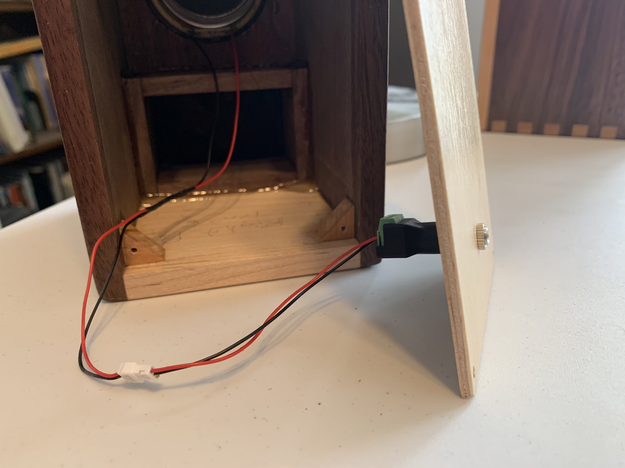
 17. Test fitting the plywood backs. |
 18. Gluing the fronts onto the boxes. |
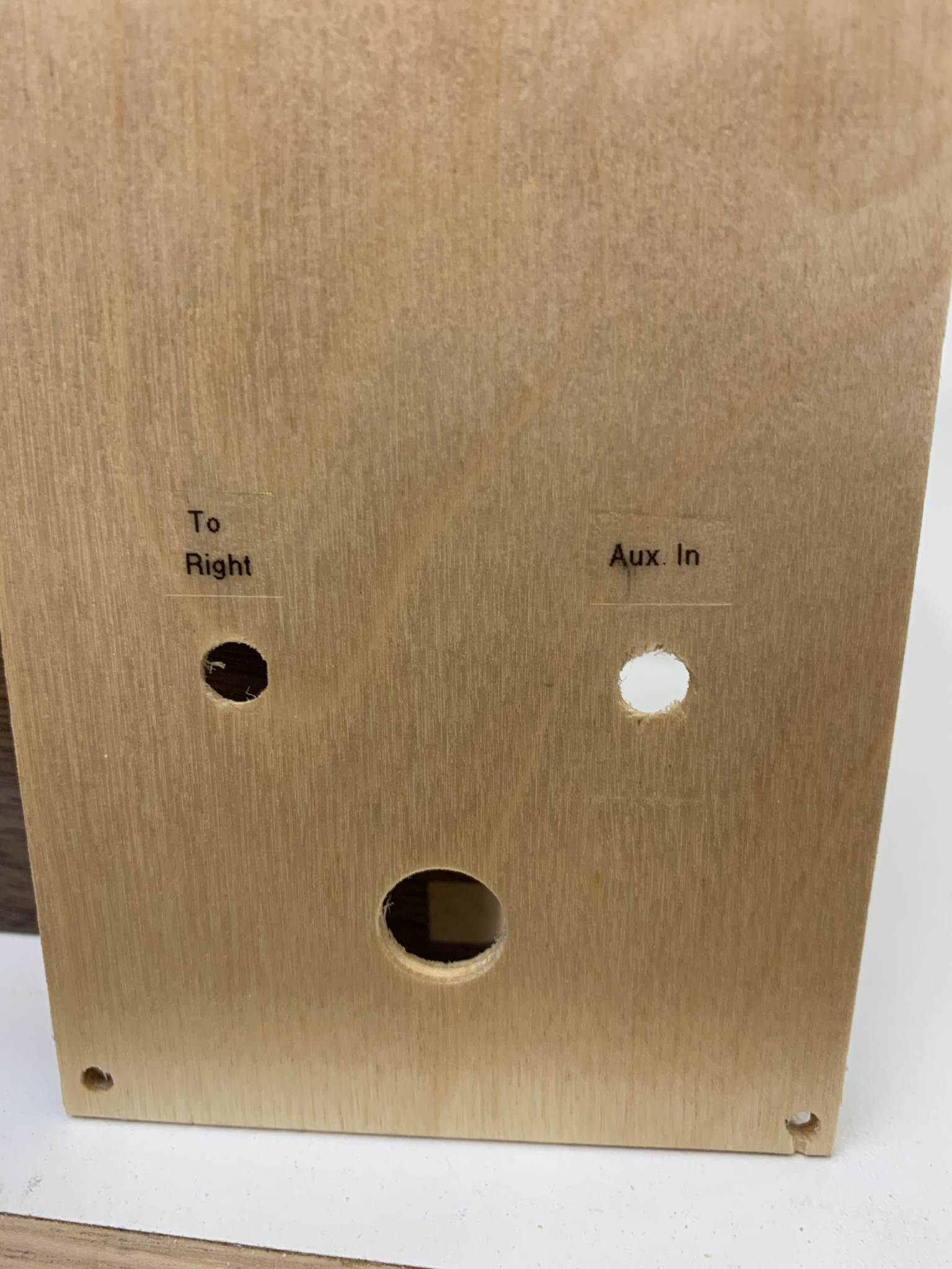
 19. After the fronts were glued on, I trimmed the panel openings flush to the sides. Then I eased the edges of the boxes and rounded over the speaker and sound port holes. |
 20. The original speakers were hardwired. I want these to be plug & play, so I started by drilling and countersinking for the jacks. |
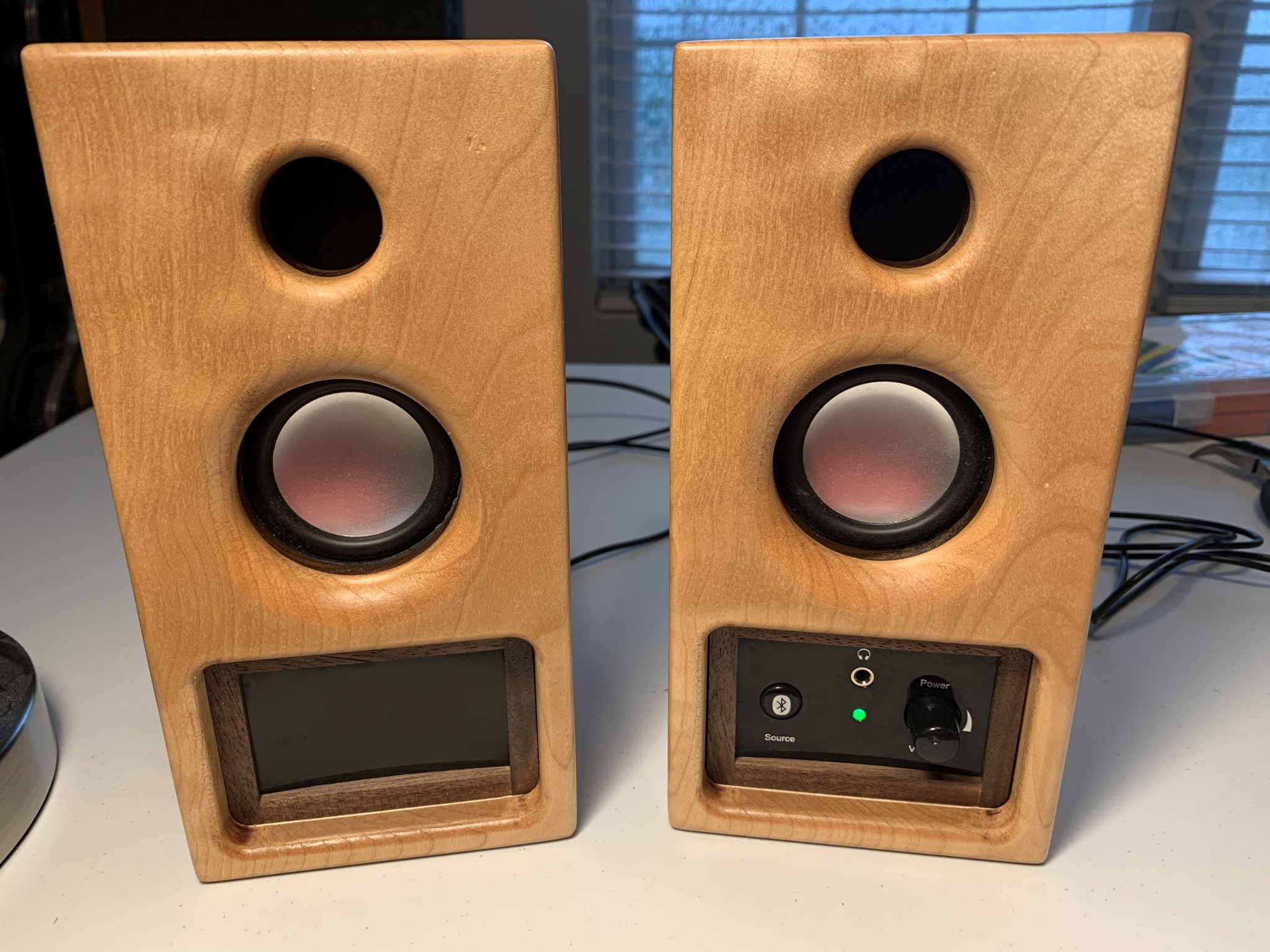
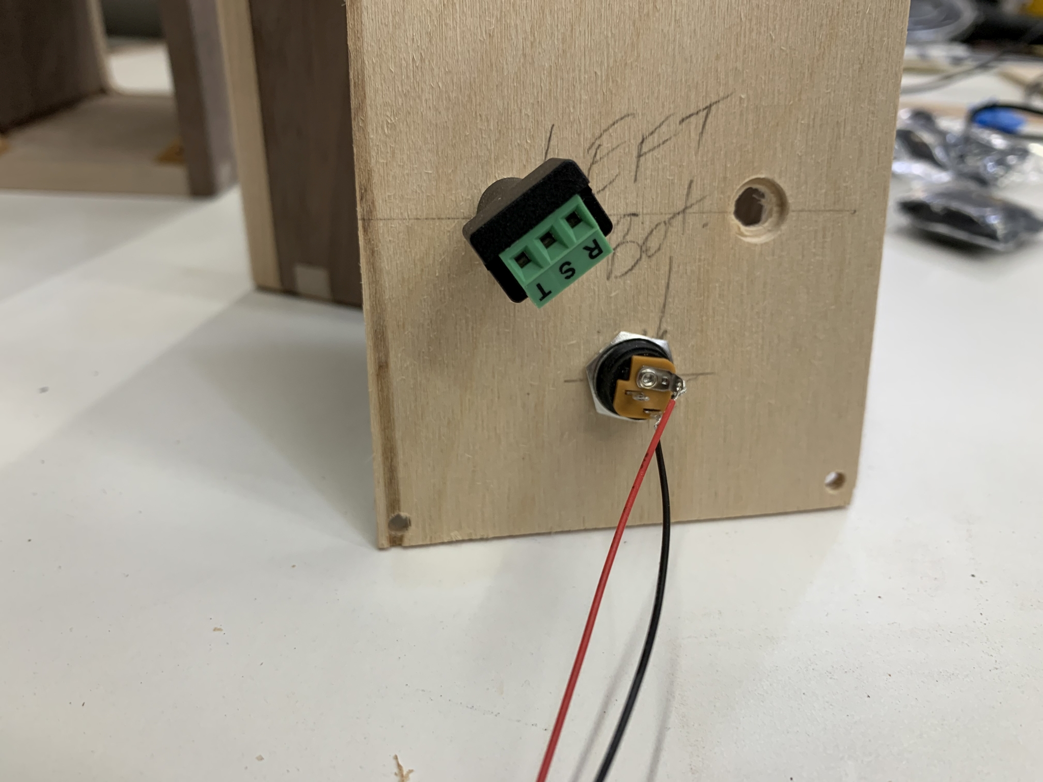 21. Here is how the jacks mount to the back panel. This is the speaker that will have the control panel in it. |
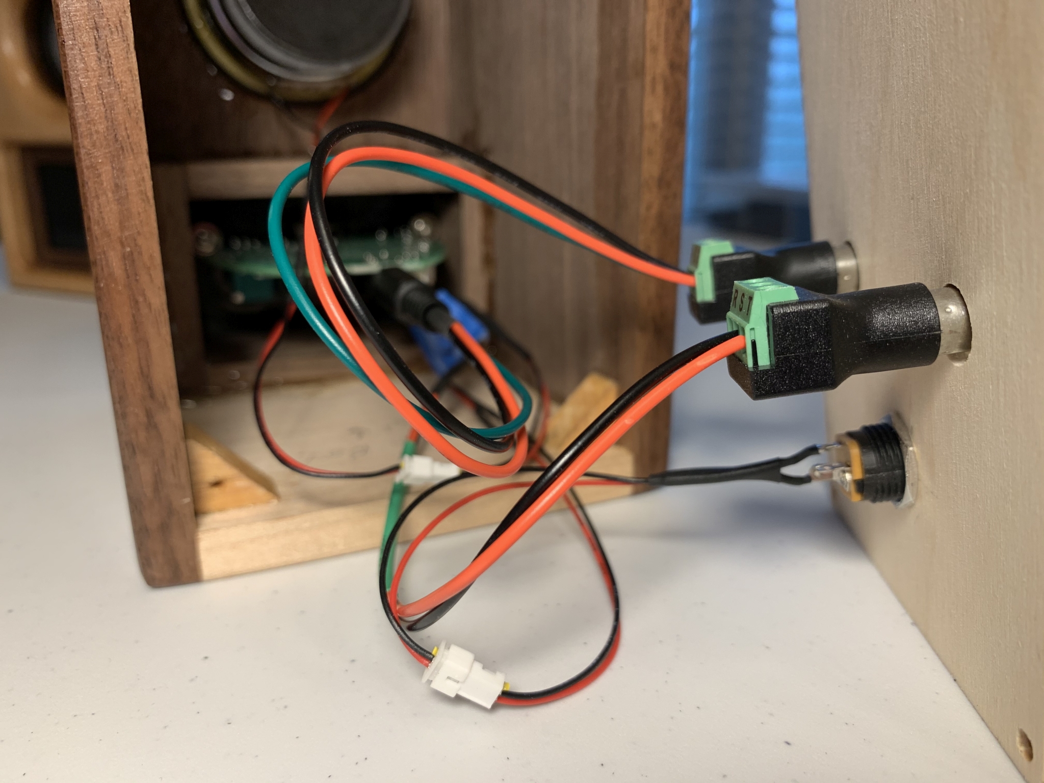
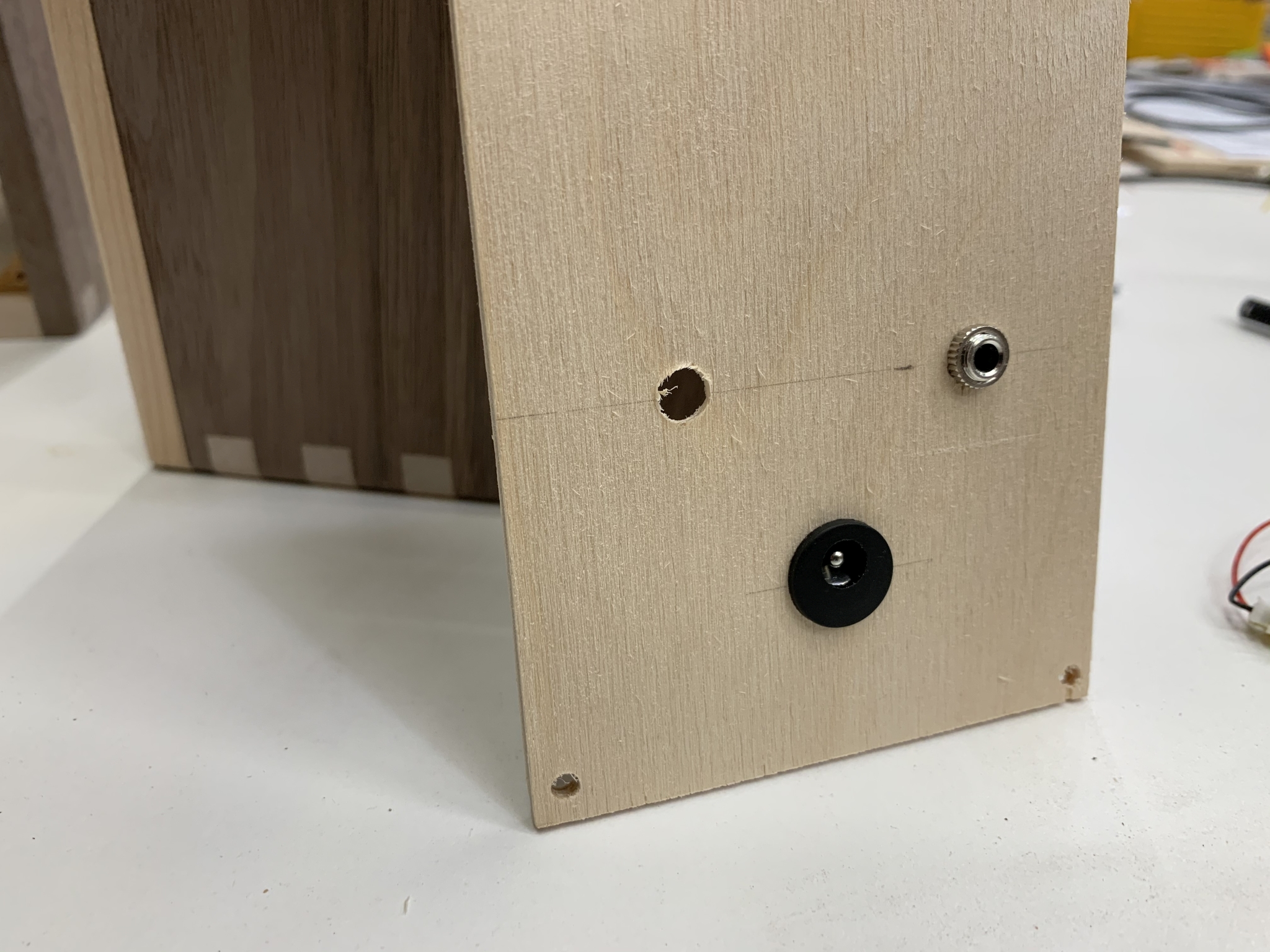 22. It will have a power jack, a 3.5mm Aux. input, and a 3.5mm jack to connect the other speaker. |
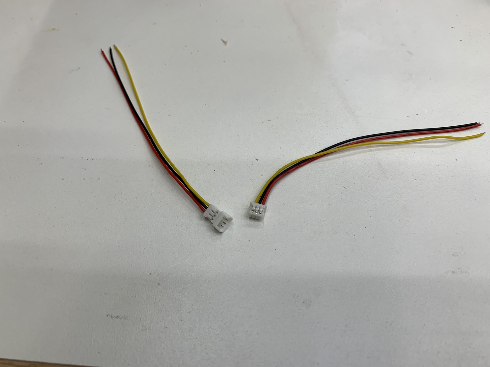 23. I am using these tiny connectors so that the back panel can be separated from the speaker box completely. |
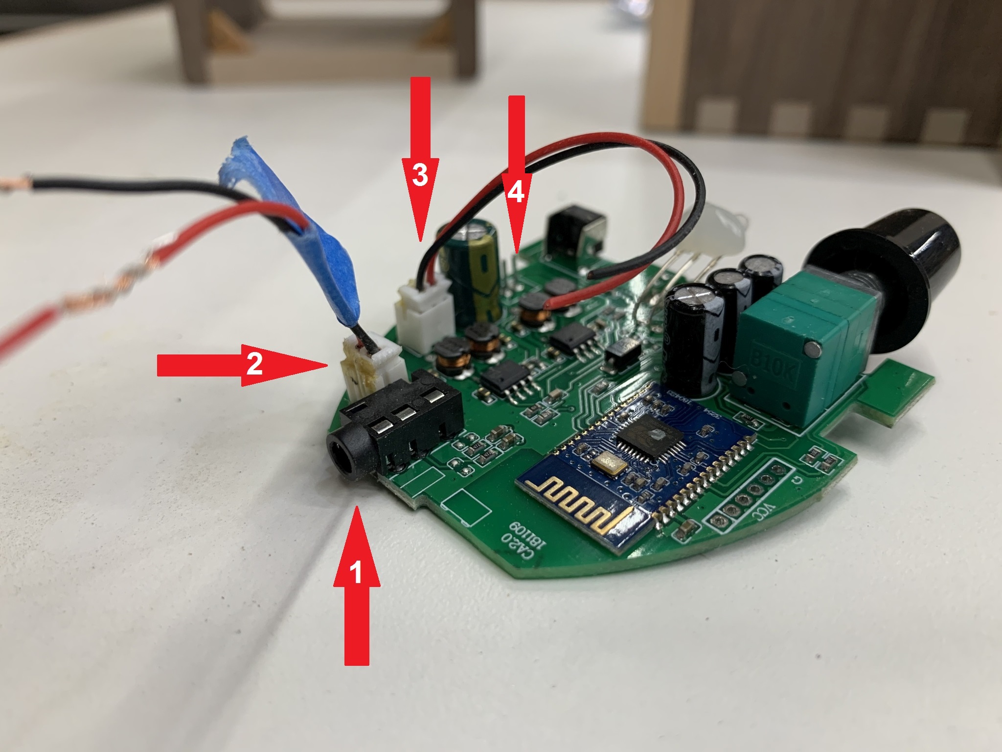 24. This is the control panel circuit board from the speakers. Arrow #1 is the Aux.-in jack. #2 is the DC power in. #3 is the connection to the other speaker. #4 is the connection for the speaker in this box. In addition, there is a headphone jack built into the front of this card that is in the control panel. |
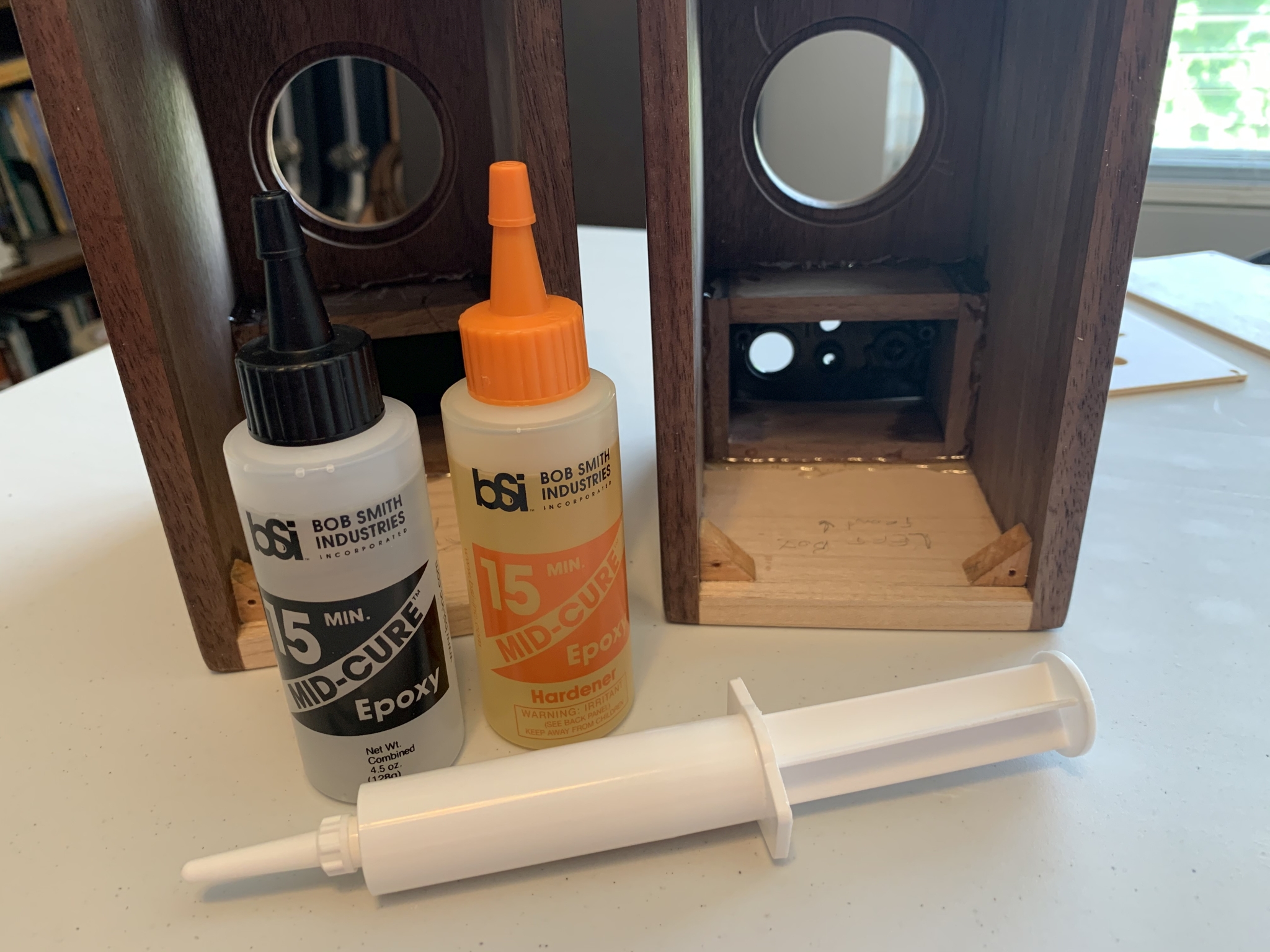
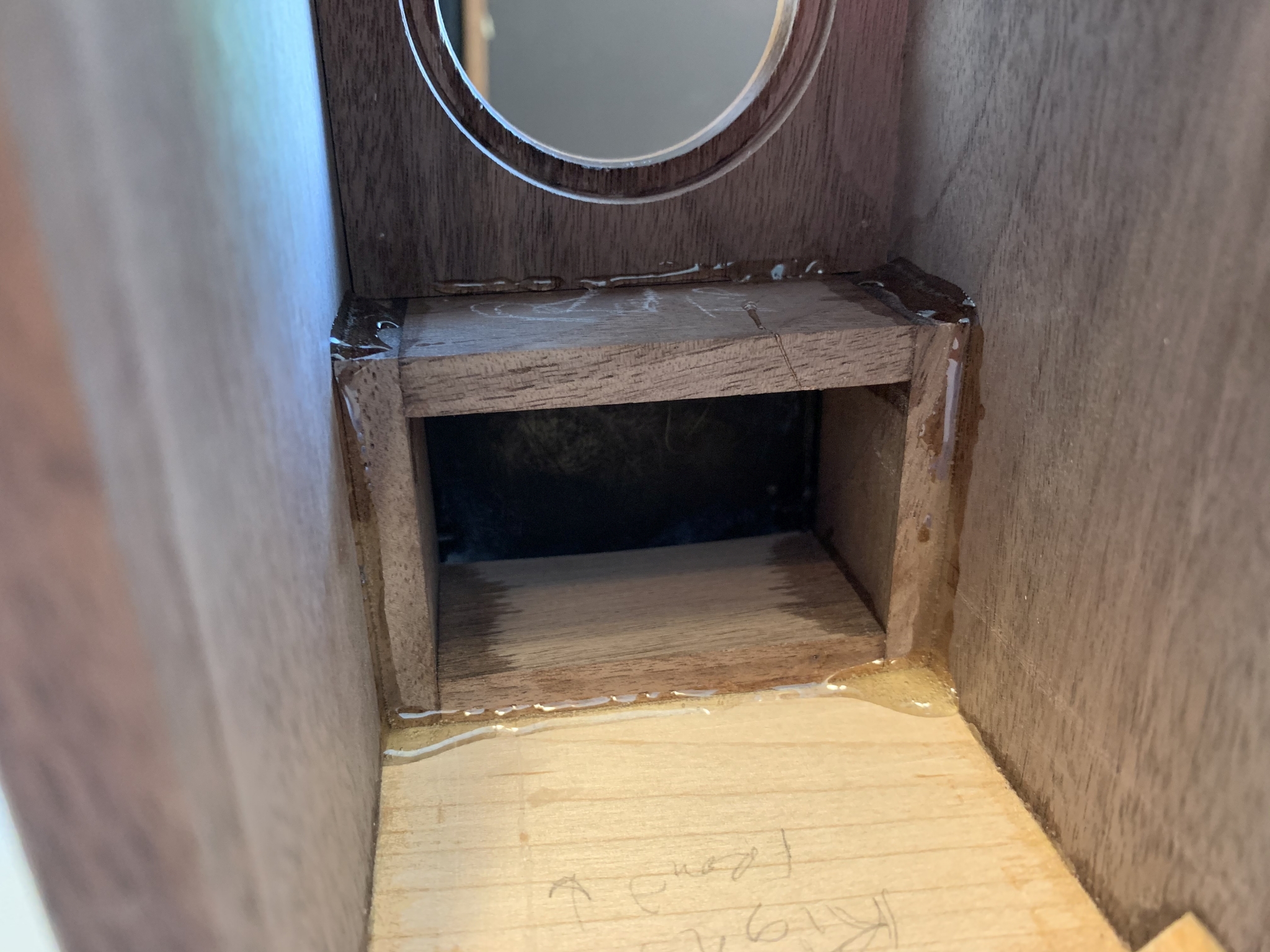
 25. Here they are after the first coat of Arm-R-Seal, a wipe-on urethane finish. |
 26. The backs got sprayed with lacquer because I wanted to embed the labels in the finish. |
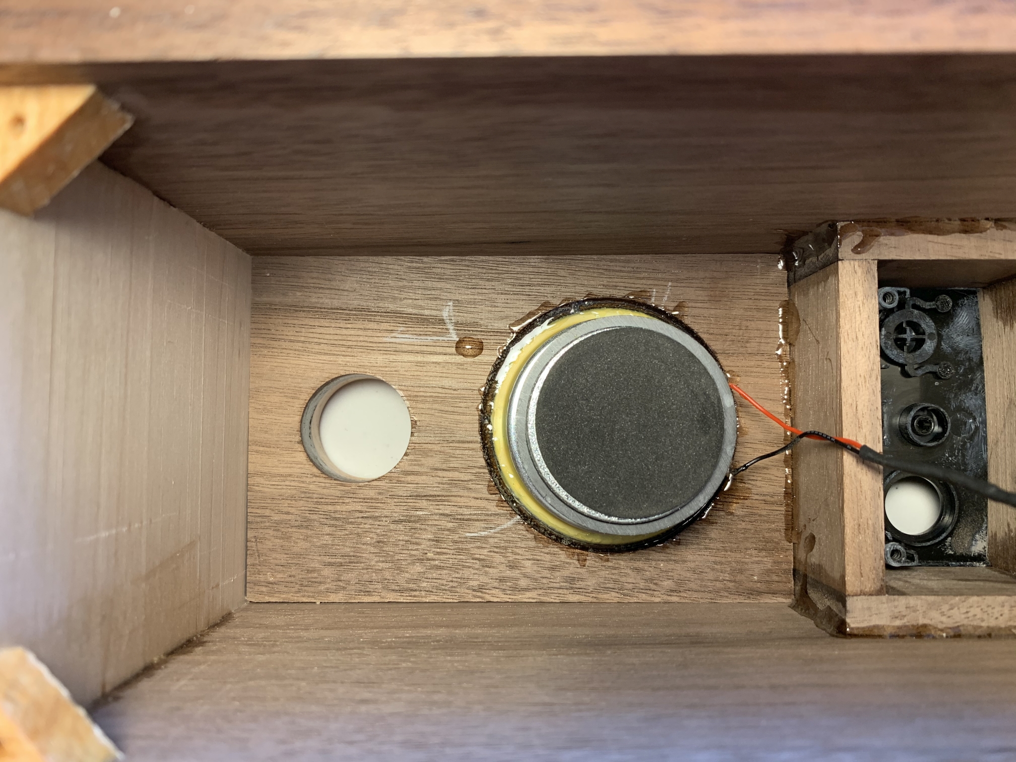
 27. After 4 coats of finish, the boxes are done. |
 28. I will be using epoxy to glue the speakers in. For the control boxes I didn't want to risk having glue seep out the front, so I decided to just use epoxy on the edges. |
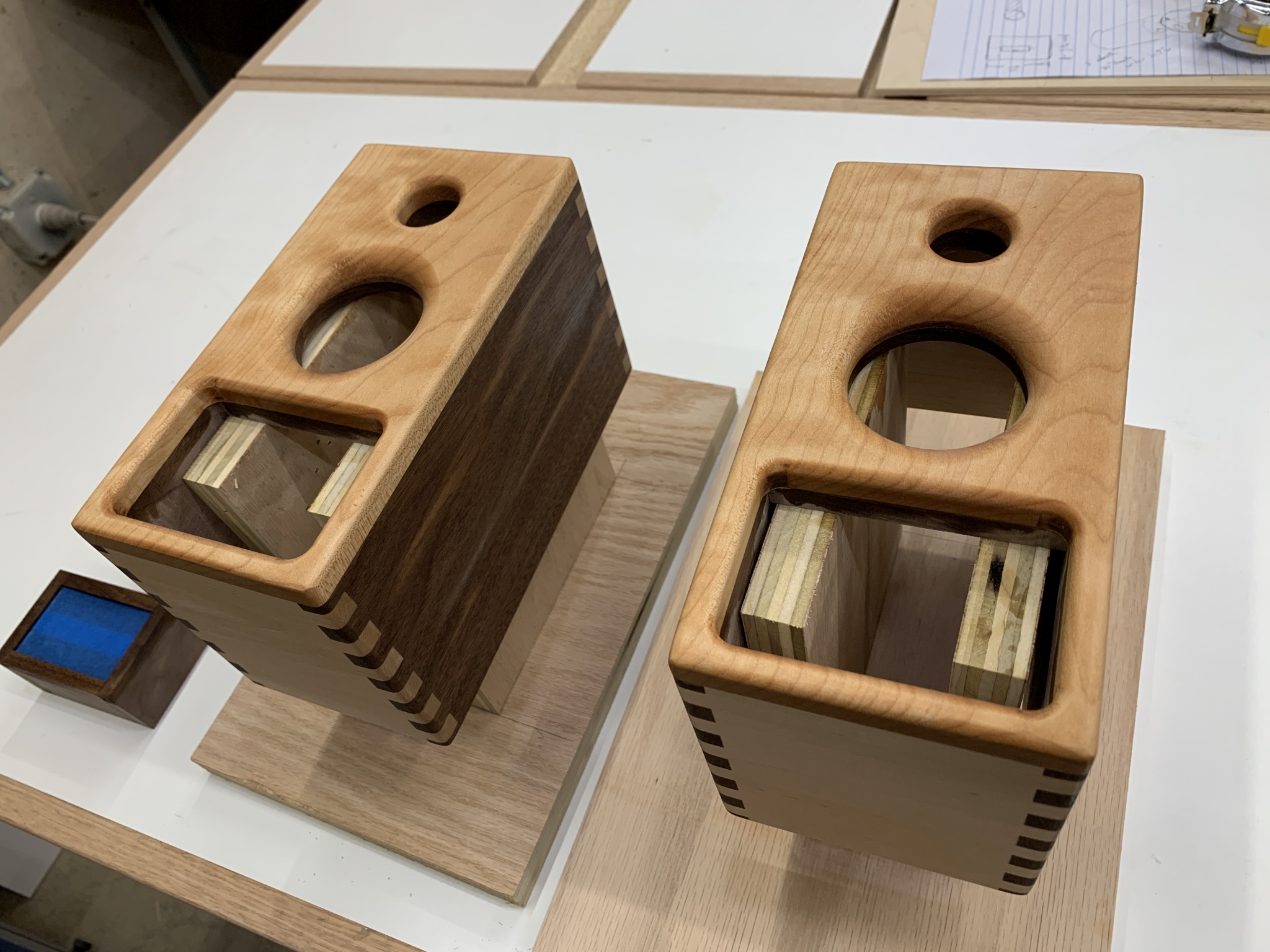
 29. It's not the neatest, but it was difficult to see while using the glue injector. |
 30. I used a smaller glue injector for the speakers. |
 31. I then used a heat gun to hopefully speed the curing of the epoxy, hoping that it won't seep under the speaker and come out the front. |
 32. Looking good at this point, now I only have to install the electronics and close them up. |
 33. Beginning assembly. The right speaker is simple, just the one speaker connection. |
 34. All closed up. |
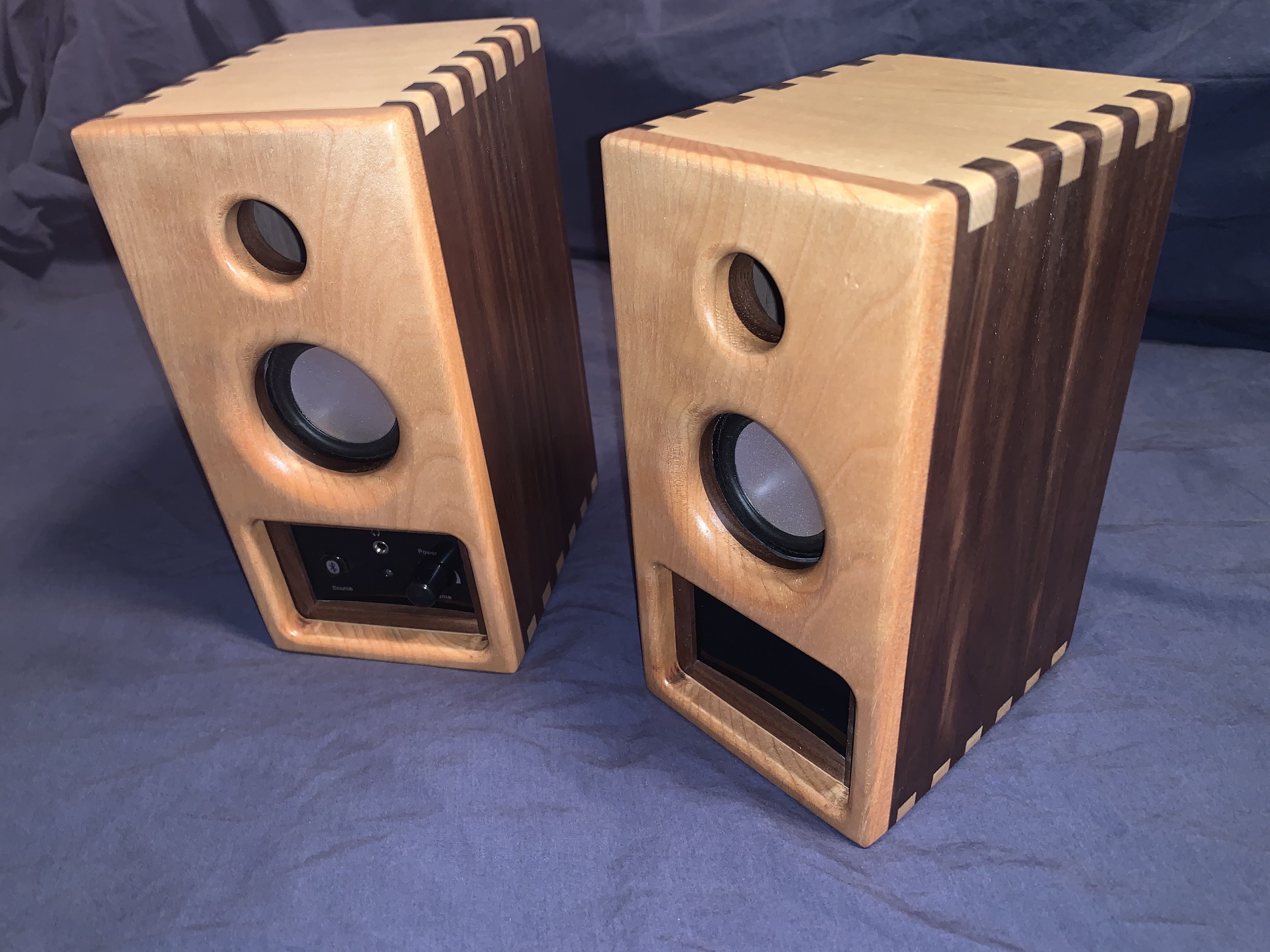
 35. The left speaker has more connections. Power, Aux. in, Right speaker out, and the connection from the left speaker to the circuit board. |
 36. All connected for testing. |
 37. Everything tested ok, so closed it up. |
 38. All finished. |